An automatic oil-gas-water three-phase separator

A three-phase separator, oil, gas and water technology, applied in the field of three-phase separation, can solve the problems of large footprint, low work efficiency, and reduced utilization of plant space, and achieve the effect of accelerated separation

Active Publication Date: 2020-08-18
CHENGGONG GASOLINEEUM SCI & TECH DONGYING
View PDF7 Cites 0 Cited by
  • Summary
  • Abstract
  • Description
  • Claims
  • Application Information

AI Technical Summary

Problems solved by technology

At present, the horizontal separator is widely used, which uses sedimentation to separate the three phases, which leads to a relatively long time-consuming, low work efficiency, and a certain structural length required for sedimentation, which in turn leads to a large footprint. Larger, reducing the space utilization rate of the factory building

Method used


Image

  • An automatic oil-gas-water three-phase separator
  • An automatic oil-gas-water three-phase separator
  • An automatic oil-gas-water three-phase separator

Examples


Embodiment Construction

[0017] In order to make the purpose, technical solutions and advantages of the embodiments of the present invention clearer, the technical solutions in the embodiments of the present invention will be clearly and completely described below in conjunction with the drawings in the embodiments of the present invention. Obviously, the described embodiments It is a part of embodiments of the present invention, but not all embodiments. Based on the embodiments of the present invention, all other embodiments obtained by persons of ordinary skill in the art without creative efforts fall within the protection scope of the present invention.

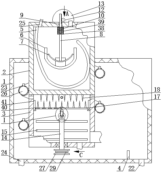
[0018]An automatic oil-gas-water three-phase separator, as shown in the figure, includes an outer shell 1, the top of the outer shell 1 is provided with an upper shell 2, the upper shell 2 penetrates the top surface of the outer shell 1 and is fixedly connected with it, the upper The bottom of the housing 2 is located inside the outer housing 1, a...


PUM


Abstract

An automatic oil-gas-water three-phase separator, comprising an outer shell, the top of the outer shell is provided with an upper shell, the bottom surface of the upper shell is fixedly connected to the top surface of the lower shell, and the bottom of the inner wall of the outer shell is vertically provided with an overflow plate, The bottom surface of the outer casing is fixedly connected to one end of the oil discharge pipe, the top surface of the upper casing is fixedly connected to one end of the exhaust pipe, and the bottom surface of the lower casing is fixedly connected to one end of the drain pipe. The U-shaped plate with the opening upwards, the U-shaped plate is provided with an upward-facing arc plate, the arc plate is fixedly connected to the lower end of the movable rod, and the top of the upper housing is provided with a guide hole for the movable rod to pass through. The device can further reduce the occupied area, ensure sufficient flow length through the spiral tube, and separate the oil phase and the liquid phase through two separations by setting the lower shell, and the content of the water phase in the liquid phase entering the shell is very small, which can The height of the overflow plate is lowered, and the fluctuation of the liquid level at the oil discharge line is also smaller.

Description

technical field [0001] The invention belongs to the field of three-phase separation, in particular to an automatic oil-gas-water three-phase separator. Background technique [0002] The three-phase separator is a device that separates the three phases of oil, gas and water in the formation fluid on the ground and accurately measures its output. At present, the horizontal separator is widely used, which uses sedimentation to separate the three phases, which leads to a relatively long time-consuming, low work efficiency, and a certain structural length required for sedimentation, which in turn leads to a large footprint. Larger, the space utilization rate of the factory building is reduced. Contents of the invention [0003] The invention provides an automatic oil-gas-water three-phase separator to solve the defects in the prior art. [0004] The present invention is achieved through the following technical solutions: [0005] An automatic oil-gas-water three-phase separa...

Claims


Application Information

Patent Timeline
Patent Type & Authority Patents(China)
IPC IPC(8): B01D19/00B01D17/038
CPCB01D17/0217B01D19/0026B01D19/0052B01D19/0057
Inventor 李冲冲王军海
Owner CHENGGONG GASOLINEEUM SCI & TECH DONGYING
Why Eureka
Try Eureka