
Data transmission method and data transmission device

A data transmission method and a technology of a data transmission device, which are applied in the field of communication, can solve problems such as low reliability, and achieve the effect of improving reliability and realizing repeated transmission

Active Publication Date: 2020-06-26
BEIJING XIAOMI MOBILE SOFTWARE CO LTD
View PDF3 Cites 13 Cited by
  • Summary
  • Abstract
  • Description
  • Claims
  • Application Information

AI Technical Summary

Problems solved by technology

For the CORESET used for PDCCH transmission, each CORESET MAC signaling will only correspondingly activate one of the multiple TCI states configured by its RRC signaling, then when the terminal receives the PDCCH sent on the CORESET, it will Using this TCI state activated by the MAC to determine the receiving beam, the reliability is relatively low

Method used


Image

  • Data transmission method and data transmission device
  • Data transmission method and data transmission device
  • Data transmission method and data transmission device

Examples


Embodiment Construction

[0045] Reference will now be made in detail to the exemplary embodiments, examples of which are illustrated in the accompanying drawings. When the following description refers to the accompanying drawings, the same numerals in different drawings refer to the same or similar elements unless otherwise indicated. The implementations described in the following exemplary examples do not represent all implementations consistent with the present disclosure. Rather, they are merely examples of apparatuses and methods consistent with aspects of the present disclosure as recited in the appended claims.

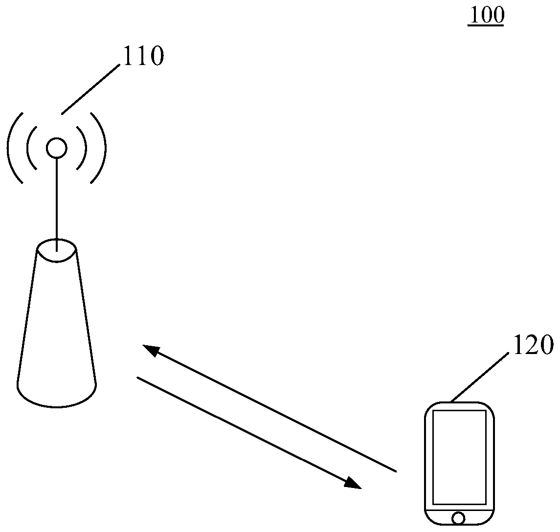
[0046] The data transmission method provided by the embodiment of the present disclosure can be applied to figure 1 In the wireless communication system 100 shown. refer to figure 1As shown, the wireless communication system 100 includes a network device 110 and a terminal 120 . The terminal 120 is connected to the network device 110 through wireless resources, and performs data tra...


PUM


Abstract

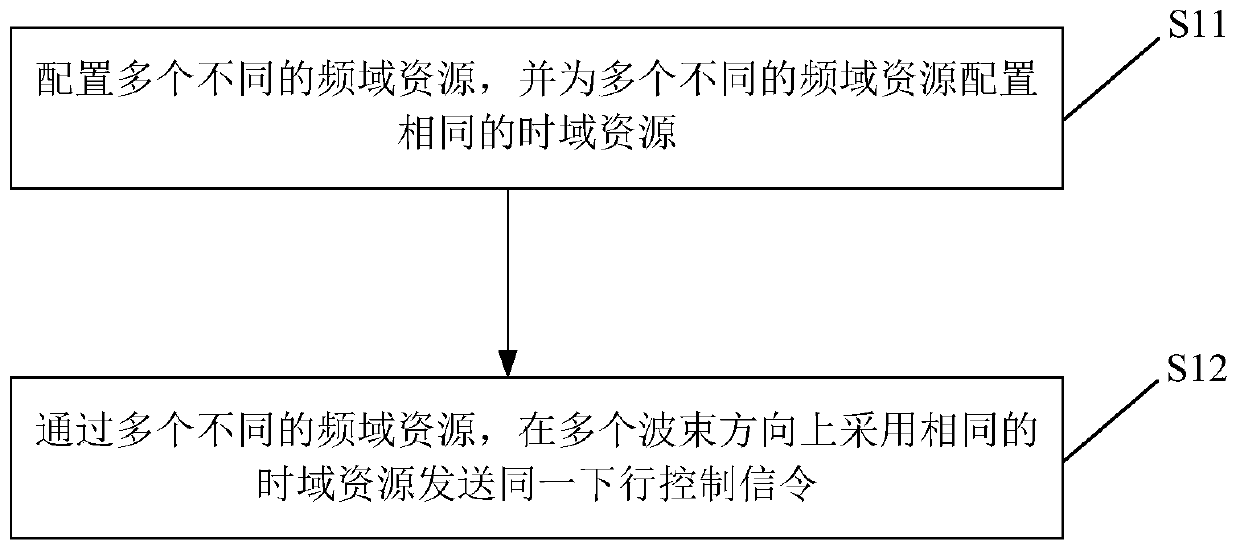
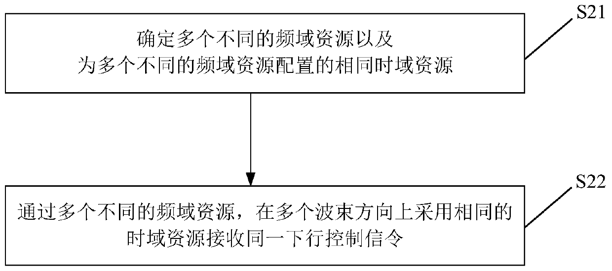
The disclosure relates to a data transmission method and a data transmission device. The data transmission method is applied to network equipment and comprises the steps of configuring a plurality ofdifferent frequency domain resources and configuring the same time domain resources for the plurality of different frequency domain resources; and sending the same downlink control signaling by the same time domain resource in a plurality of wave beam directions through the plurality of different frequency domain resources. By the method and the device, the same downlink control signaling can be repeatedly sent, and the communication reliability can be improved.

Description

technical field [0001] The present disclosure relates to the field of communication technologies, and in particular, to a data transmission method and a data transmission device. Background technique [0002] In a new wireless technology (New Radio, NR), in order to ensure coverage and resist path loss, it is generally necessary to perform data transmission based on a beam (beam). [0003] During beam-based data transmission, a network device (such as a base station) indicates a Transmission Configuration Indication (TCI) status or spatial relation information (spatial relation info) through signaling, and then indicates a receiving beam or a transmitting beam of a terminal. Wherein, each TCI state or each spatial relationship information corresponds to a reference signal (Reference Signal, RS) identifier, and the RS can be a non-zero power channel state information reference signal (Channel State Information Reference Signal, CSI-RS) or It is a synchronization signal block...

Claims


Application Information

Patent Timeline
Patent Type & Authority Applications(China)
IPC IPC(8): H04L5/00H04W72/04
CPCH04L5/0048H04W72/53H04W72/23H04W72/044H04W72/046H04B7/0695H04W72/0453H04L5/0053H04L5/0094H04W72/0446
Inventor 李明菊
Owner BEIJING XIAOMI MOBILE SOFTWARE CO LTD
Learn More