Resonance suppression method and system for electrolytic-capacitor-free variable-frequency driving system

A technology of variable frequency drive and resonance suppression, which is applied in the direction of electronically commutated motor control, motor control, motor generator control, etc., can solve the problems of power factor drop, current harmonic increase, etc., to reduce clamping time, reduce Power grid current harmonics and the effect of improving current quality

Active Publication Date: 2020-06-26
HUAZHONG UNIV OF SCI & TECH
View PDF6 Cites 5 Cited by
  • Summary
  • Abstract
  • Description
  • Claims
  • Application Information

AI Technical Summary

Problems solved by technology

[0006] Aiming at the above defects or improvement needs of the prior art, the present invention provides a resonance suppression method and system for a variable frequency drive system without electrolytic capacitors, the purpose of which is to solve the problem that the current active damping control method does not consider the bus voltage pumping during motor braking. The situation, resulting in the increase of current harmonics, the technical problem of power factor drop

Method used


Image

  • Resonance suppression method and system for electrolytic-capacitor-free variable-frequency driving system
  • Resonance suppression method and system for electrolytic-capacitor-free variable-frequency driving system
  • Resonance suppression method and system for electrolytic-capacitor-free variable-frequency driving system

Examples


Embodiment Construction

[0042] In order to make the object, technical solution and advantages of the present invention clearer, the present invention will be further described in detail below in conjunction with the accompanying drawings and embodiments. It should be understood that the specific embodiments described here are only used to explain the present invention, not to limit the present invention. In addition, the technical features involved in the various embodiments of the present invention described below can be combined with each other as long as they do not constitute a conflict with each other.

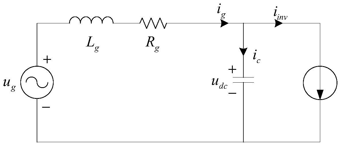
[0043] figure 2 It is the small signal equivalent circuit diagram of permanent magnet synchronous motor variable frequency drive system without electrolytic capacitor, in the figure i g Input current for the grid, i c Input current for the bus capacitor, u dc is the bus voltage, i inv Input current for the inverter. The inverter and the motor can be equivalent to a variable current source,...


PUM


Abstract

The invention discloses a resonance suppression method and system for an electrolytic-capacitor-free variable-frequency drive system, and belongs to the field of drive control of permanent magnet synchronous motors. The method comprises the steps: multiplying a bus voltage resonance component by the feedback proportional gain to obtain a damping current of the system; multiplying a damping currentby a current bus voltage to obtain equivalent damping power of the input side of an inverter, and converting LC oscillation of the input side of a driving system to the output side of the inverter; dividing the equivalent damping power of the input side of the inverter by the current output current of the inverter to obtain the equivalent damping output voltage of the inverter, and superposing the equivalent damping output voltage to the damping voltage of the alpha axis and the damping voltage of the beta axis according to the current of the alpha axis and the beta axis of the motor, so thatresonance components are absorbed by the current of the motor, and LC resonance suppression is realized. According to the invention, the LC resonance in the driving system can be effectively suppressed, the power factor of the driving system without the electrolytic capacitor can be improved, the calculation is simple, and the digital realization is easy.

Description

technical field [0001] The invention belongs to the technical field of drive control of permanent magnet synchronous motors, and more specifically relates to a resonance suppression method and system for a variable frequency drive system without an electrolytic capacitor. Background technique [0002] In the traditional AC-DC-AC variable frequency drive system, due to the existence of electrolytic capacitors, the entire variable frequency drive system is bulky, costly, and has a low service life. At the same time, the input power factor is low and there are grid-side current harmonics. Film capacitors or ceramic capacitors replace traditional electrolytic capacitors, that is, variable frequency drive systems without electrolytic capacitors. [0003] The topology of the main circuit of the permanent magnet synchronous motor variable frequency drive system without electrolytic capacitors is as follows: figure 1 As shown in the figure, L g , C dc Input inductance and bus cap...

Claims


Application Information

Patent Timeline
Patent Type & Authority Applications(China)
IPC IPC(8): H02P21/22H02P21/14H02P21/05H02P25/024H02P27/06
CPCH02P21/22H02P21/14H02P21/05H02P25/024H02P27/06H02P2207/05H02P2209/11H02P29/50Y02P80/10
Inventor 尹泉李海春罗慧刘洋
Owner HUAZHONG UNIV OF SCI & TECH
Why Eureka
Try Eureka