Old Wire Stripper

A technology of stripping machine and old wires, applied in the direction of circuits, electrical components, electronic waste recycling, etc., can solve the problems of single wire stripping machine mechanism, insufficient wire clamping force, and incomplete peeling of the skin of the wire.

Active Publication Date: 2021-05-04
工牛电缆河北有限公司
View PDF5 Cites 1 Cited by
  • Summary
  • Abstract
  • Description
  • Claims
  • Application Information

AI Technical Summary

Problems solved by technology

[0002] When some wires and cables are used for a long time, they will be replaced, and the replaced old wires and cables are not worthless. The copper wires inside it can be reused. Generally, workers will use scissors to remove them. The rubber skin of the old wire, but its efficiency is very low in the manual way, so a wire stripping machine has been developed, but the traditional wire stripping machine has a single mechanism. For example, the Chinese utility model patent with the publication number CN205123149U discloses a stripping machine The wire device includes a wire stripper body, the wire stripper body includes a wire stripping mechanism and a wire stripper handle, the wire stripping mechanism includes an upper pliers body and a lower pliers body, one end of the upper pliers body is hinged to one end of the lower pliers body, and the wire stripper The handle of the tool is connected to the hinged end of the wire stripping mechanism; the inner sides of the upper pliers body and the lower pliers body are equipped with stripping grooves, and arc-shaped blades are arranged in the wire stripping grooves, and the wire stripping grooves on the upper pliers body and the lower pliers body The position and shape of the upper stripping groove are symmetrical; when the upper pliers body and the lower pliers body are close to each other, the wire stripping groove on the upper pliers body and the wire stripping groove on the lower pliers body combine to form a wire stripping area. The blades of the curved blades in the stripping slot combine to form a perfect circle
But this utility model comprises the following problems: 1, single on the overall structure, the clamping force for electric wire is not enough, may cause the epidermis of electric wire not to peel off completely; high

Method used


Image

  • Old Wire Stripper
  • Old Wire Stripper
  • Old Wire Stripper

Examples


Embodiment

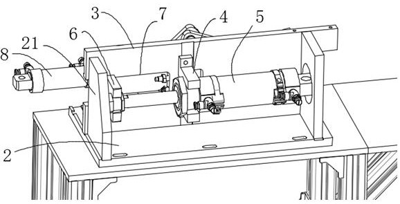
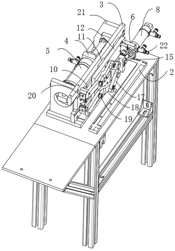
[0023] Embodiment: old electric wire stripping machine, constitutes as figure 1 As shown, including the base 1, the base 1 is provided with a positioning plate 2, the side of the positioning plate 2 near the moving plate 6 is provided with a limit block 21, the positioning plate 2 is provided with an upright plate 3, and the upright plate 3 A connecting rod limiting block 22 is provided on the side close to the connecting rod fixing seat 15, and a cylinder fixing seat 4 is provided on the rear side of the upright plate 3, and the first cylinder 5 is clamped on the cylinder fixing seat 4, and the first cylinder 5 The extension end is provided with a movable plate 6, such as figure 2 As shown, the limit block 22 can effectively limit the stroke of the first cylinder 5, avoiding the failure caused by the first cylinder 5 exceeding its own stroke; the upright plate 3 is provided with a rectangular gap 7, and the moving plate 6 is arranged on the rectangular gap 7, the end of the...


PUM


Abstract

The invention discloses an old electric wire stripping machine, which comprises a base (1), a positioning plate (2) is arranged on the base (1), an upright plate (3) is arranged on the positioning plate (2), and the rear side of the upright plate (3) A cylinder fixed seat (4) is provided, and a first cylinder (5) is clamped on the cylinder fixed seat (4), and a moving plate (6) is provided on the protruding end of the first cylinder (5); the upright plate (3) is provided with a rectangular notch (7), the moving plate (6) is set in the rectangular notch (7), the end of the moving plate (6) is provided with a second cylinder (8), and the second cylinder (8) A connection block (9) is provided on the protruding end. The invention can effectively clamp the electric wires, remove the rubber surface layer of the electric wires better, has high working efficiency and is convenient to use.

Description

technical field [0001] The present invention relates to the field of electric wire processing equipment, especially old electric wire stripping machines. Background technique [0002] When some wires and cables are used for a long time, they will be replaced, and the replaced old wires and cables are not worthless. The copper wires inside it can be reused. Generally, workers will use scissors to remove them. The rubber skin of the old wire, but its efficiency is very low in the manual way, so a wire stripping machine has been developed, but the traditional wire stripping machine has a single mechanism. For example, the Chinese utility model patent with the publication number CN205123149U discloses a stripping machine The wire device includes a wire stripper body, the wire stripper body includes a wire stripping mechanism and a wire stripper handle, the wire stripping mechanism includes an upper pliers body and a lower pliers body, one end of the upper pliers body is hinged t...

Claims


Application Information

Patent Timeline
Patent Type & Authority Patents(China)
IPC IPC(8): H01B15/00
CPCH01B15/00Y02W30/82
Inventor 卢成绩林礼区廖志温文文金江成王家伦
Owner 工牛电缆河北有限公司
Why Eureka
Try Eureka