
Laser scanning measurement device and method for tool cutting test platform

A laser scanning and cutting test technology, which is applied in the direction of measuring devices, optical devices, and testing machinability, can solve the problems of time-consuming and labor-intensive, large measurement errors, etc., and achieve simple structure, easy adjustment, and convenient and fast measurement methods. Effect

Pending Publication Date: 2020-06-26
SHANGHAI TUNNEL ENG CO LTD +1
View PDF16 Cites 0 Cited by
  • Summary
  • Abstract
  • Description
  • Claims
  • Application Information

AI Technical Summary

Problems solved by technology

[0005] The traditional method of measuring the outline of a stone is usually to manually measure the width and depth of each position of the broken stone or the cut stone by using measuring tools such as calipers and tapes. After a large amount of measurement data, the stone is obtained. The effect diagram of the outline. This method usually needs to move the stone during the measurement process, so it is only suitable for the measurement of small stones; the traditional method of measuring the tool is usually to disassemble the tool, and manually use a caliper to measure on the tool. The diameter at different tangent points is compared with the standard diameter to obtain the wear of the tool. This method requires the tool to be disassembled before the measurement can be started
[0006] Both of the above two traditional measurement methods have the disadvantages of large measurement errors, time-consuming and labor-intensive

Method used


Image

  • Laser scanning measurement device and method for tool cutting test platform
  • Laser scanning measurement device and method for tool cutting test platform
  • Laser scanning measurement device and method for tool cutting test platform

Examples


Embodiment Construction

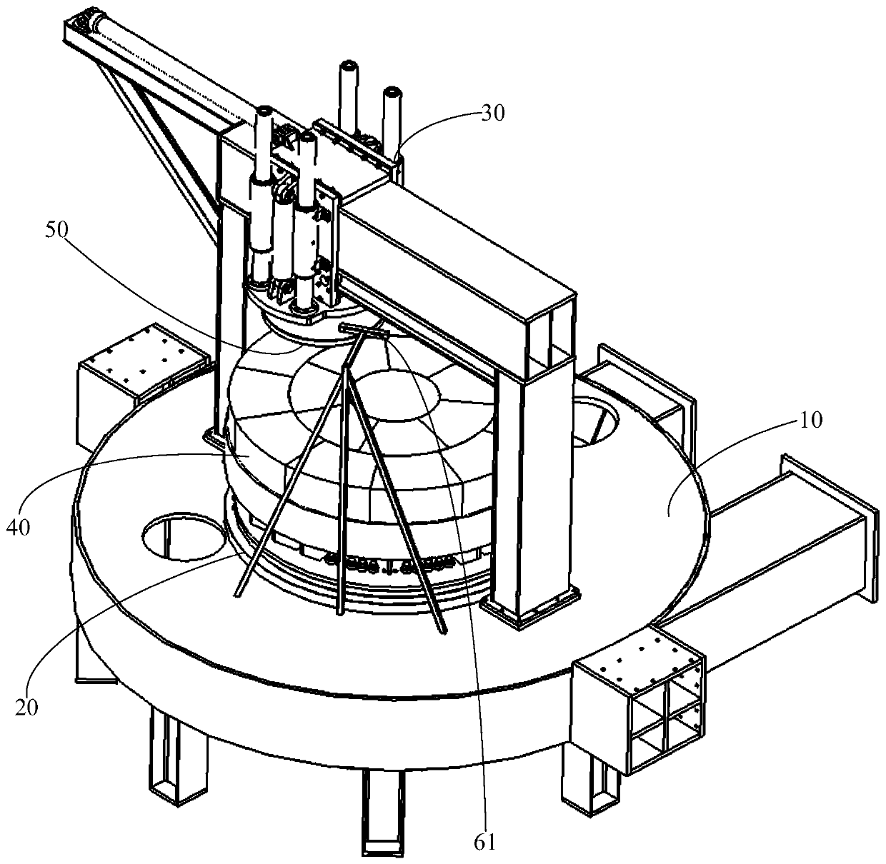
[0038] Since the tool cutting test platform needs to measure the contour of the cut stone after each simulated cutting test, in order to judge whether the cutting test parameters can achieve the expected cutting effect, if not, then according to the measurement results, the test The parameters are analyzed and adjusted in order to achieve the best test parameters for actual construction; in addition, in the process of cutting test, it is also necessary to measure the wear of the tool in order to obtain the service life of each tool under different cutting conditions , to facilitate timely replacement of the tool in actual construction.

[0039] The traditional method of measuring the contour of a stone usually needs to move the stone during the measurement process, so it is only suitable for the measurement of smaller stones; the traditional method of measuring the tool needs to be disassembled before the measurement can be started. The measurement process More troublesome. M...


PUM


Abstract

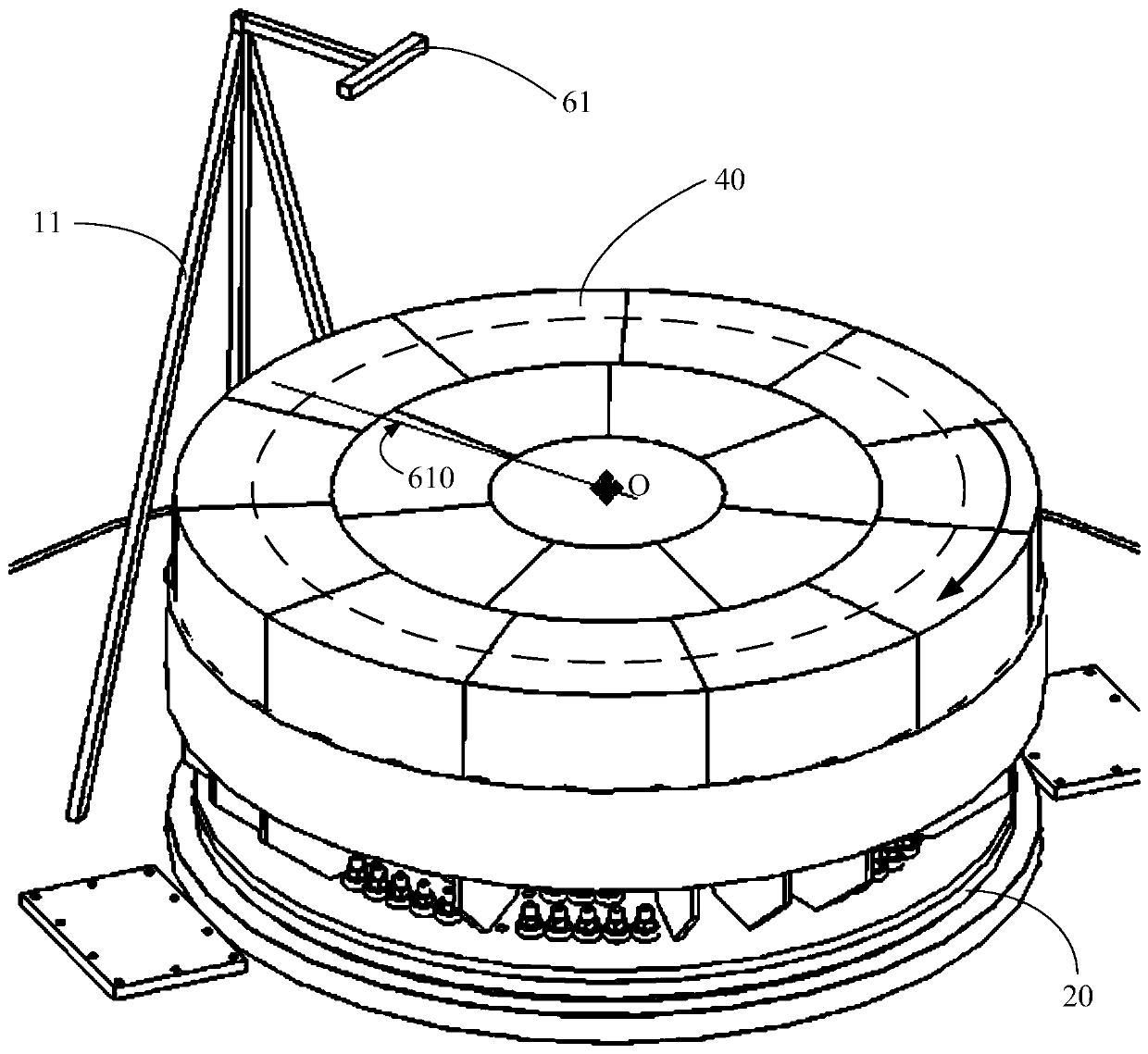
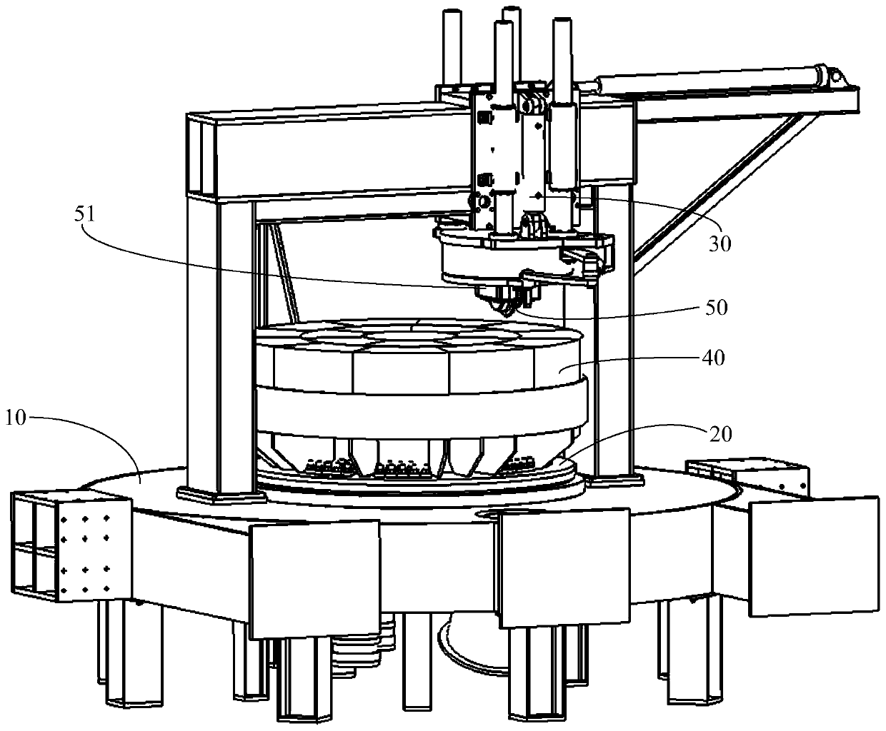
The invention relates to a laser scanning measurement device and method for a tool cutting test platform. The test platform comprises a rotating mechanism, a stone disc connected to the top of the rotating mechanism, a lifting mechanism erected above the stone disc and a tool connected to the bottom of the lifting mechanism. The laser scanning measurement device comprises a computer, a first lasersensor used for emitting first line laser distributed in the radial direction of the stone disc to the stone disc, and an encoder used for collecting the rotation angle of the stone disc. The computer is in control connection with the first laser sensor and the encoder. The special structure of the cutter cutting test platform is matched, the laser sensor is used for carrying out laser scanning on the rotating stone disc, the outline of the stone disc can be rapidly and accurately scanned, the test effect can be conveniently observed and analyzed, good test parameters can be conveniently adjusted and obtained, the measurement device is simple in structure, the measurement method is more convenient and faster, the measuring result is accurate, and the time cost and the labor cost are saved.

Description

technical field [0001] The invention belongs to the technical field of tunnel detection, and in particular relates to a laser scanning measurement device and a measurement method for a tool cutting test platform. Background technique [0002] The traditional tool cutting test platform usually adopts the cutting method of fixed stone plate and rotating tool with reference to the actual construction method. The cutting track of the tool is fixed, that is to say, one tool can only be used for simulated cutting test for one application. If To simulate cutting tests for more applications, it is necessary to arrange multiple cutting tools on one radius of the stone plate, which undoubtedly increases the cost. [0003] In response to the above problems, a new type of tool cutting test platform with a structure of rotating stone discs and fixed tools has appeared on the market, which can realize simulated cutting tests at different positions with only one tool, and avoids the cuttin...

Claims


Application Information

Patent Timeline
Patent Type & Authority Applications(China)
IPC IPC(8): G01N3/58G01N3/06G01N3/02G01B11/24
CPCG01N3/58G01N3/068G01N3/02G01B11/24G01N2203/0053G01N2203/0641
Inventor 袁玮皓黄德中杨正彭世宝徐天明张弛李钦孙骏庄欠伟蒋宏亮陈琦李若涵颜洪宇黄志龙李炎龙桂诗玉陆杰
Owner SHANGHAI TUNNEL ENG CO LTD
Learn More