Eureka AIR delivers breakthrough ideas for toughest innovation challenges, trusted by R&D personnel around the world.

Cleaning system

A cleaning system and a technology to be cleaned, applied in the field of cleaning systems, can solve the problems of not being able to completely remove sodium, increasing the difficulty of cleaning equipment with sticky sodium, etc.

Active Publication Date: 2020-06-26
CHINA INSTITUTE OF ATOMIC ENERGY
View PDF7 Cites 4 Cited by
  • Summary
  • Abstract
  • Description
  • Claims
  • Application Information

AI Technical Summary

Problems solved by technology

[0003] At present, the cleaning process of sodium-sticking equipment is usually carried out in the cleaning trap. Since the sodium on the surface of the sodium-sticking equipment is removed by participating in a chemical reaction during the cleaning process, it is necessary to continuously maintain a slight positive pressure and an inert atmosphere in the cleaning well. In order to realize the control of the cleaning process; in addition, there is a method of cleaning sodium sticky equipment by means of sodium distillation in the vacuum cleaning container, but this method cannot completely remove sodium, and this method needs to vacuumize the cleaning container
The cleaning system of sodium sticky equipment in the prior art usually needs to be equipped with a vacuum cleaning trap or a cleaning container. The above-mentioned cleaning device cannot completely remove sodium, and the preparation of a vacuum environment increases the cleaning difficulty of the sodium sticky equipment, and in order to reduce potential safety hazards. The gas monitoring device continuously monitors the gas generated during the cleaning process

Method used


Image

  • Cleaning system
  • Cleaning system
  • Cleaning system

Examples


Embodiment 1

[0039] Taking the sodium valve as an example, a cleaning method in the embodiment of the present invention is further described.

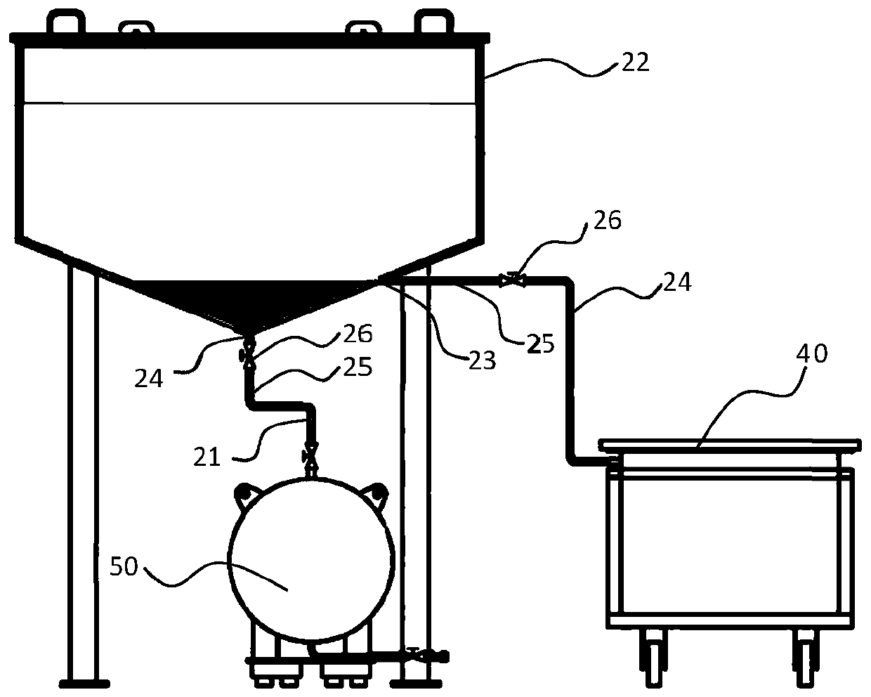
[0040] Move the equipment to be cleaned to the transport module 10 (using a sealable temporary storage tank in this embodiment) by the clamping module 60 (an electric crane is used in this embodiment), and the first cleaning agent is used in the temporary storage tank to cover the equipment to be cleaned. Impurities on the surface of the equipment are sealed in the temporary storage tank and transported to the first cleaning module 20 .

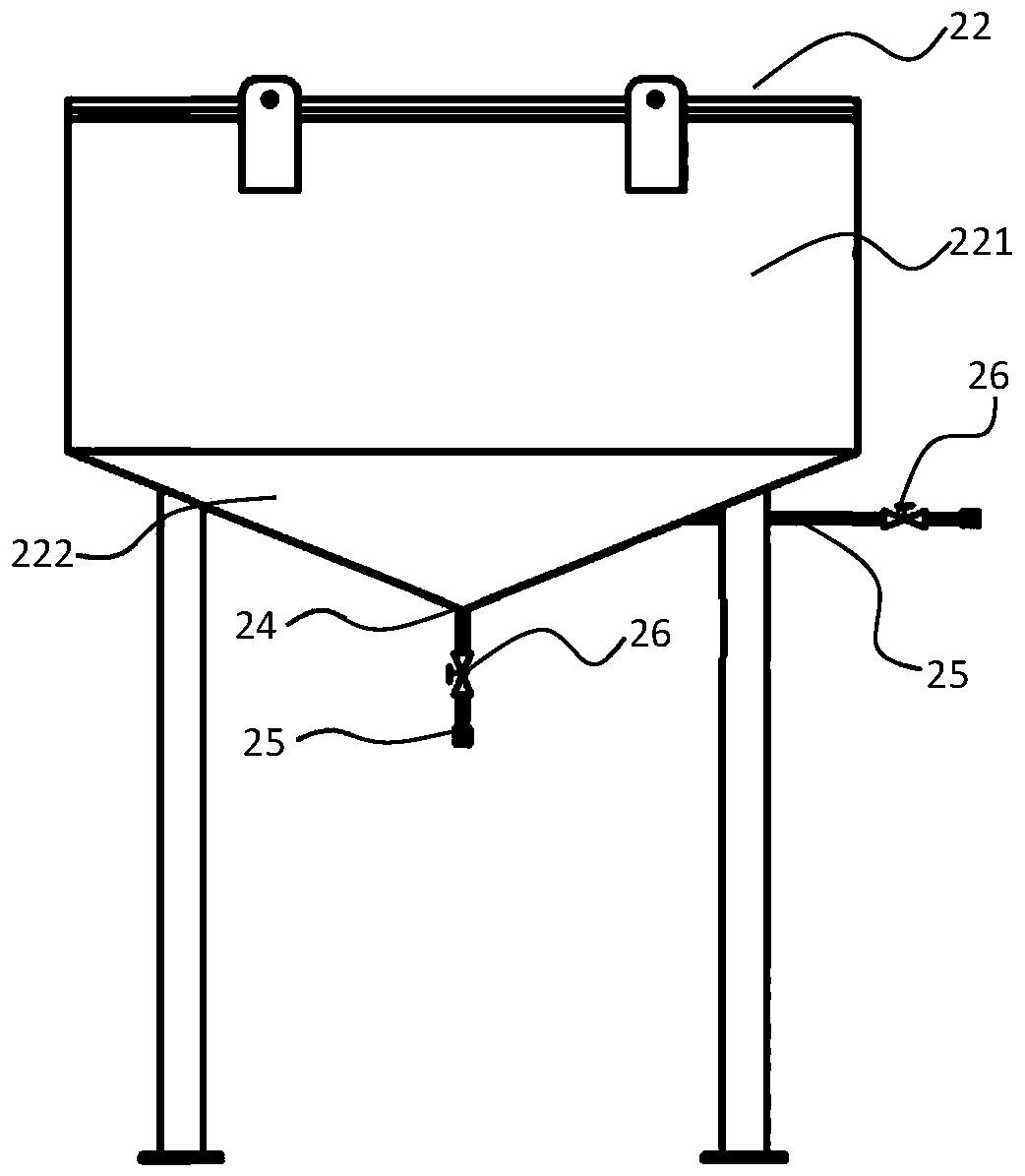
[0041] Add the first cleaning agent (paraffin oil is used in this embodiment) in the cleaning tank 22 of the first cleaning module 20, use an electric crane to transfer the equipment to be cleaned to the cleaning tank 22, and use an electric heating wire to heat the cleaning tank 22, so that impurities Desorb from the surface of the equipment to be cleaned, and drive the equipment to be cleaned to move up and down...


PUM


Abstract

The invention discloses a cleaning system. The cleaning system comprises a conveying module which is configured to isolate equipment to be cleaned in the moving process from air, a first cleaning module which is provided with an accommodating space for the equipment to be cleaned and a first cleaning agent and comprises an output pipeline which is used for discharging the first cleaning agent andimpurities and a heating system which is used for maintaining the first cleaning module at a preset temperature, a recovery module which is used for sequentially collecting the impurities of the firstcleaning agent and the equipment to be cleaned when the recovery module communicates with the first cleaning module through the output pipeline, a second cleaning module which is provided with an accommodating space for the equipment to be cleaned and a second cleaning agent, a clamping module which is configured to drive the equipment to be cleaned to move and an adjusting module which is configured to provide an accommodating space for controlling the clamping module to move.

Description

technical field [0001] Embodiments of the present invention relate to the technical field of reactor equipment cleaning, in particular to a cleaning system. Background technique [0002] During the operation of a reactor with sodium as the coolant, the equipment used in the sodium circuit needs to be cleaned for sodium removal during replacement and maintenance. The cleaning of sodium-sticking equipment requires that the sodium on the equipment be completely removed as much as possible and minimize Waste that needs to be further processed, to avoid corrosion of equipment by products of sodium participating in chemical reactions, to avoid hydrogen explosions, etc. [0003] At present, the cleaning process of sodium-sticking equipment is usually carried out in the cleaning trap. Since the sodium on the surface of the sodium-sticking equipment is removed by participating in a chemical reaction during the cleaning process, it is necessary to continuously maintain a slight positi...

Claims


Application Information

Patent Timeline
Patent Type & Authority Applications(China)
IPC IPC(8): B08B3/08B08B3/10B08B13/00
CPCB08B3/08B08B3/10B08B13/00
Inventor 王荣东谢淳杨红义姚泽文朴君杜海鸥李君瑜
Owner CHINA INSTITUTE OF ATOMIC ENERGY
Why Eureka
Eureka Blog
Learn More