Manufacturing method of luminous bead curtain
A production method and bead curtain technology, applied in the field of home decoration, can solve problems such as problems, difficult to popularize and apply, and achieve the effects of bright brightness, improved brightness consistency, and long luminous length.
- Summary
- Abstract
- Description
- Claims
- Application Information
AI Technical Summary
Problems solved by technology
Method used
Image

Examples
Embodiment 1
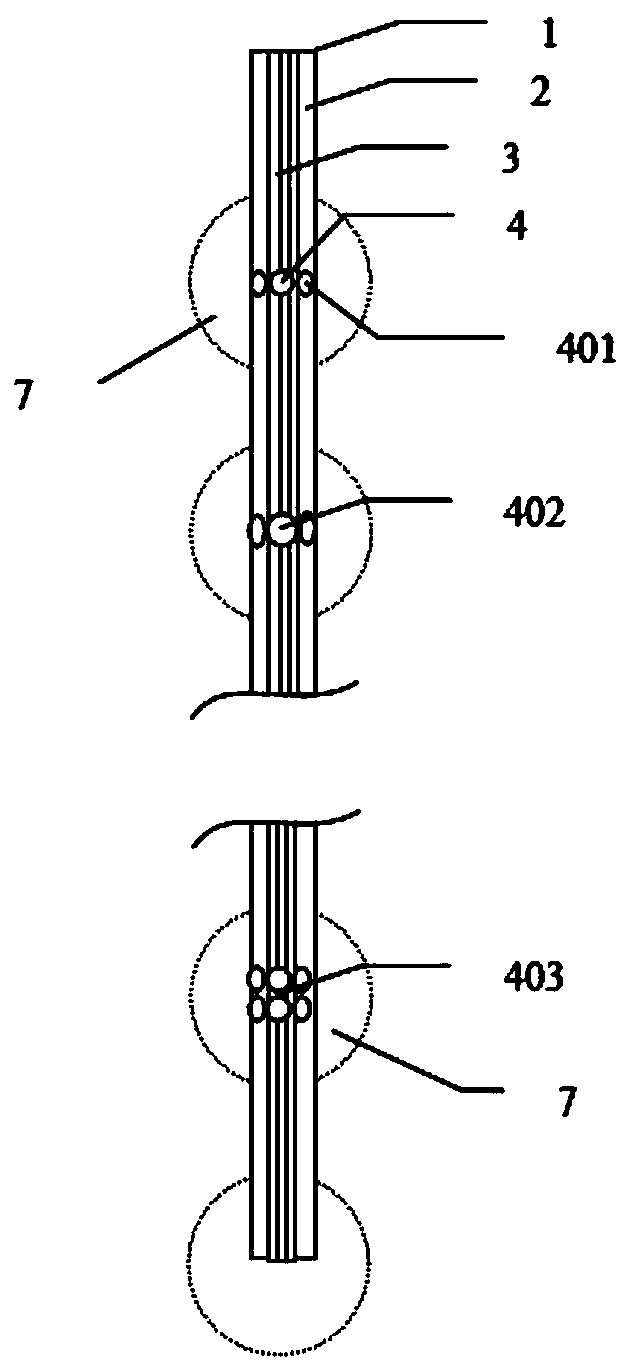
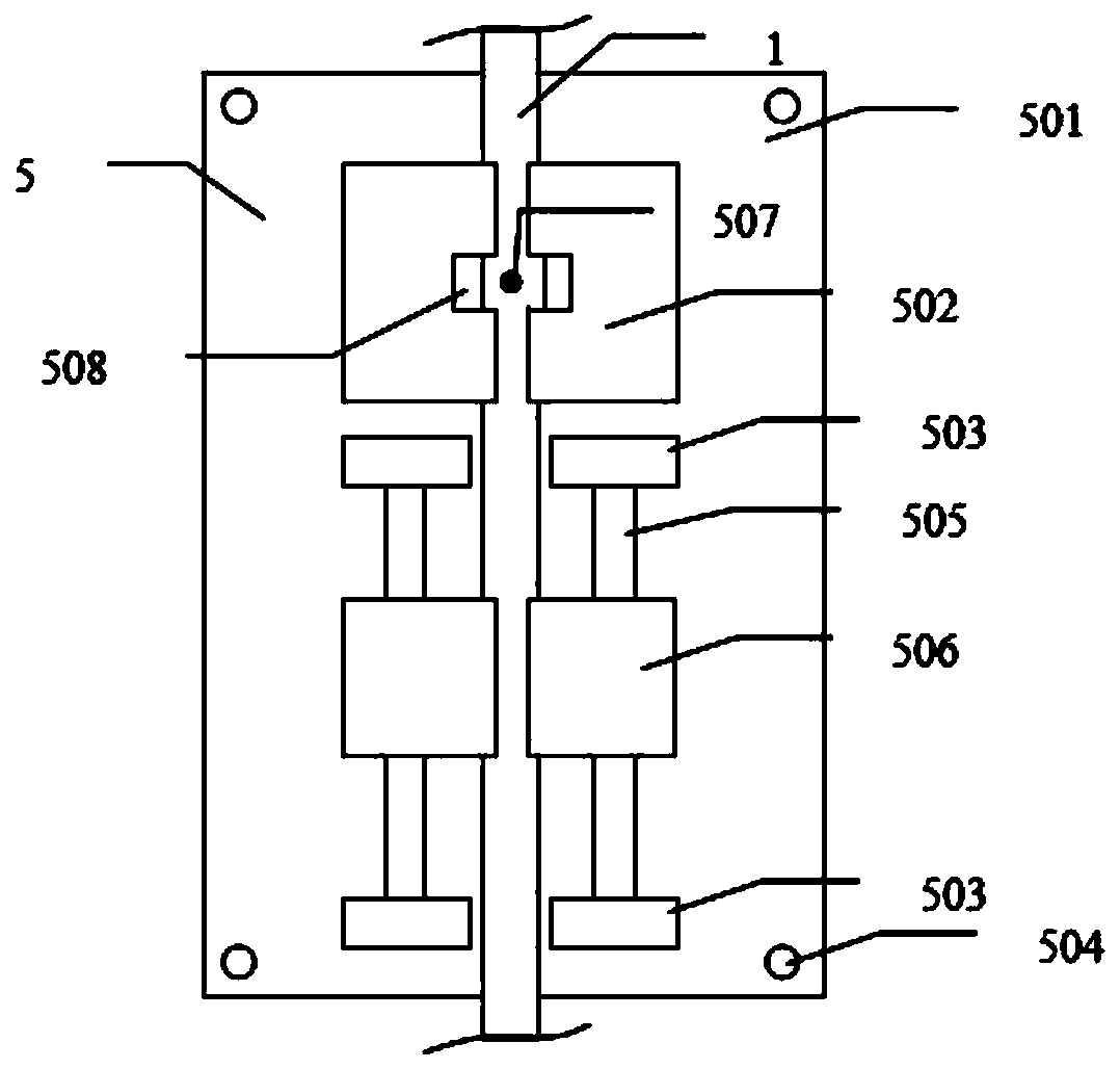
[0043] A drilling and milling mechanical engraving machine or a laser engraving machine and an optical fiber processing fixture are used to form a pit 4 on the surface of the plastic optical fiber 1 to remove the cladding 2 and expose the fiber core 3. The schematic diagram of the pit structure is shown in figure 1 . The plastic optical fiber processing fixture 5, the structure diagram is shown in figure 2 The plastic optical fiber processing fixture 5 is composed of a fixture base 501, a positioning seat 502, a bracket 503, a positioning hole 504, a slide rail 505 and a slider 506, etc., and the positioning hole 504 on the fixture base 501 fixes the fixture on the working platform of the engraving machine. Positioning seat 502 is assisted by slide block 506, through electric control circuit ( figure 2(not shown in the figure) completes actions such as clamping, loosening and rotating the plastic optical fiber 1. The slider 506 assists the positioning seat 502 to complete t...
Embodiment 2
[0045] The plastic optical fiber is cut into sections, the cuts at both ends are ground and polished, and placed in figure 2 In the shown plastic optical fiber processing jig, the cutter is located above the processing point 507, and the plastic optical fiber 1 is controlled to rotate 360 degrees in the positioning seat 502. Under the control of the slider 506, cut the 3mm long cladding 2 flatly, and then rotate 360 degrees in the positioning seat 502, and the cutter cuts off the cladding 2 at another position of the plastic optical fiber 1. The above actions are repeated every 4cm to cut off the cladding length. Gradually increase from the coupling end of the LED light source, remove the loose cladding 2, Figure 5 The left is a schematic diagram of the optical fiber cladding removal structure. The plastic optical fiber 1 removes the cladding and fills the mixture of photoluminescent phosphor and silica gel in the pit where the cladding is removed and the core is expose...
Embodiment 3
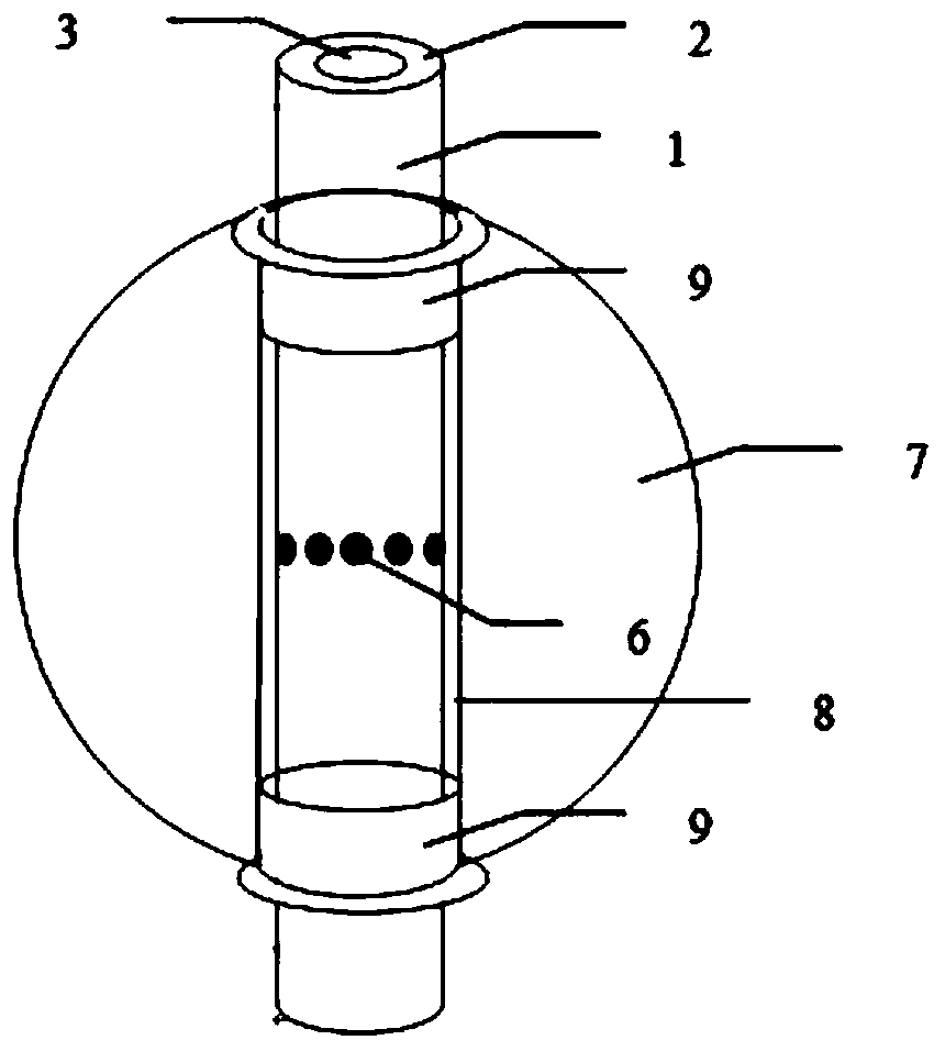
[0047] The process of removing the cladding of the plastic optical fiber is the same as in the second embodiment, and the cavity 4 where the plastic optical fiber 1 is clad removed and the core is exposed is not filled with phosphor. The inner wall of the columnar through hole 8 in the center of the bead 7 is coated with a layer of silica gel 6 containing photoluminescent phosphor powder, the two ends of the columnar through hole 8 in the center of the bead 7 are inserted into the transition plug 12, and the transition plug 16 is removed after heating and curing. Figure 7 It is a schematic diagram of the structure of beads, transition plug and inner coating phosphor. Thread the plastic optical fiber with the cladding removed, and the cladding removal place is located in the center of the beaded column-shaped through hole. Insert the plastic optical fiber positioning support 9 at both ends of the beaded columnar through hole, and fix the positioning support 9 with but not limi...
PUM
| Property | Measurement | Unit |
|---|---|---|
| Wavelength | aaaaa | aaaaa |
Abstract
Description
Claims
Application Information
 - R&D
- Intellectual Property
- Life Sciences
- Materials
- Tech Scout
- Unparalleled Data Quality
- Higher Quality Content
- 60% Fewer Hallucinations
Browse by: Latest US Patents, China's latest patents, Technical Efficacy Thesaurus, Application Domain, Technology Topic, Popular Technical Reports.
© 2025 PatSnap. All rights reserved.Legal|Privacy policy|Modern Slavery Act Transparency Statement|Sitemap|About US| Contact US: help@patsnap.com