Ultrahigh-precision digital pulse signal generation circuit and method

A signal generation circuit and digital pulse technology, applied in the direction of pulse generation, electric pulse generation, pulse technology, etc., can solve the problems of not being able to reflect changes in time accuracy in time, consuming hardware resources, system execution time, and increasing the complexity of circuit physical design, etc. problem, to achieve the effect of easy realization, simple structure and wide range of pulse frequency

Active Publication Date: 2020-06-23
HUNAN GREAT LEO MICROELECTRONICS CO LTD
View PDF5 Cites 4 Cited by
  • Summary
  • Abstract
  • Description
  • Claims
  • Application Information

AI Technical Summary

Problems solved by technology

The calibration program not only consumes a certain amount of hardware resources and system execution time, but also can only be calibrated according to a fixed mode and cycle, and cannot reflect changes in time accuracy in a timely manner
ADI uses full hardware to implement the calibration mechanism, but it needs to add an additional delay unit on the basis of the delay chain to shift the edge to achieve calibration, which not only increases the complexity of the physical design of the circuit, but also increases the delay. The unit itself will also be affected by factors such as voltage, temperature, process, etc., which will affect the time accuracy after calibration

Method used


Image

  • Ultrahigh-precision digital pulse signal generation circuit and method
  • Ultrahigh-precision digital pulse signal generation circuit and method
  • Ultrahigh-precision digital pulse signal generation circuit and method

Examples


Embodiment Construction

[0059] The present invention will be further described in detail below in conjunction with the accompanying drawings and specific embodiments.

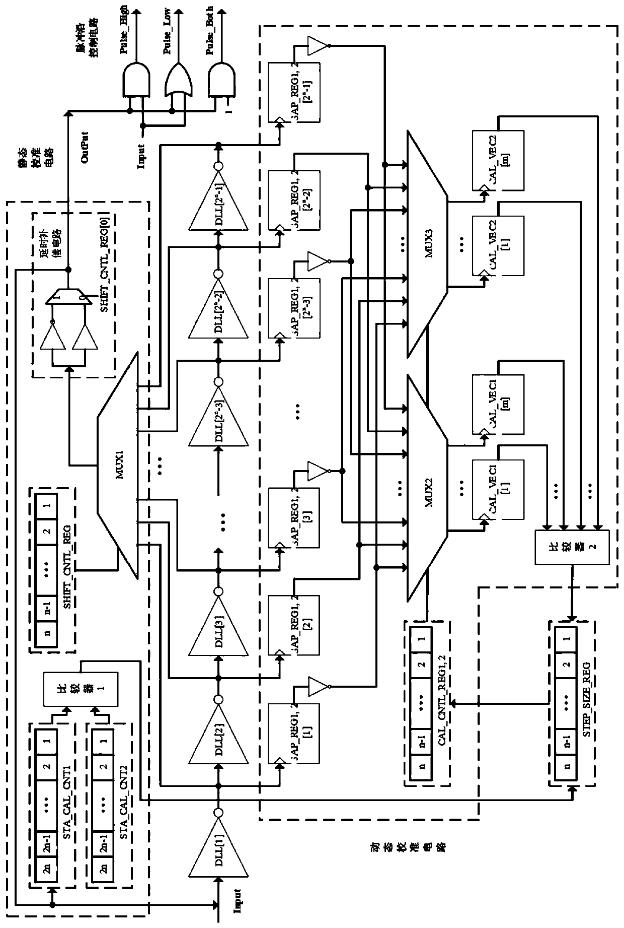
[0060] Such as figure 2 As shown, the ultra-high precision digital pulse signal generating circuit of the present invention includes:

[0061] The pulse edge control circuit is used to generate a certain amount of delay to the signal on the input pin Input (such as the signal output by traditional PWM), and precisely control the position of the rising edge and falling edge of the pulse signal, thereby accurately controlling the width of the pulse, Generate ultra-high precision pulses.

[0062] The static calibration circuit is used to calculate the step size information representing the relationship between the system working clock cycle and the delay of the delay unit at the beginning of the system power-on operation. That is, how many delay units the signal can propagate and pass through within one system clock cycle, and the inf...


PUM


Abstract

The invention discloses an ultrahigh-precision digital pulse signal generation circuit and method, and the circuit comprises a pulse edge control circuit which is used for generating a certain amountof time delay for a signal on an input pin Input, and precisely controlling the positions of a rising edge and a falling edge of a pulse signal, thereby precisely controlling the width of a pulse, andgenerating an ultrahigh-precision pulse; the static calibration circuit is used for calculating step length information representing the relationship between the working clock period of the system and the delay of a delay unit in the pulse edge control circuit at the beginning of power-on work of the system, and storing the step length information; wherein the step length information is the number of delay units through which the signal propagates in a system clock period; and the dynamic calibration circuit is used for dynamically calculating the step length information in real time when therising edge or the falling edge of each pulse on the input pin Input comes. The method is implemented based on the circuit. The invention has the advantages of simple structure, easiness in implementation, high precision, wide supported pulse frequency range and the like.

Description

technical field [0001] The invention mainly relates to the technical field of digital signal processors, in particular to an ultra-high-precision digital pulse signal generation circuit and method. Background technique [0002] Pulse Width Modulation (PWM, Pulse Width Modulation) is a method of controlling the level of an analog signal using a digital output, and its function is mathematically equivalent to a digital-to-analog converter (Digital-to-Analog Converter). PWM technology is one of the core technologies of frequency conversion technology. It is widely used in many fields such as measurement, communication, power / speed control and conversion of power supply / motor. Typical applications include: grid power conversion, frequency conversion air conditioner, switching (digital) power supply, robot Motor servo control, smart meter, etc. [0003] Usually, the PWM circuit used in digital signal processor (DSP) and other integrated circuits to modulate the pulse signal widt...

Claims


Application Information

Patent Timeline
Patent Type & Authority Applications(China)
IPC IPC(8): H03K3/017H03K3/011H03K7/08
CPCH03K3/017H03K3/011H03K7/08H03K5/133H03K4/026H03K21/406
Inventor 陈虎许野万江华
Owner HUNAN GREAT LEO MICROELECTRONICS CO LTD
Why Eureka
Try Eureka