
Inductive current zero-crossing detection method of bridgeless power factor correction circuit

A technology of power factor correction and inductance current, which is applied in the direction of output power conversion device, conversion of AC power input to DC power output, high-efficiency power electronic conversion, etc., which can solve the problem that the signal is easily interfered by noise, the power factor is reduced, and the malfunction And other problems, to achieve the effect of accurate action, power factor improvement, and enhanced stability

Inactive Publication Date: 2020-06-23
SHANGHAI INST OF SPACE POWER SOURCES
View PDF6 Cites 9 Cited by
  • Summary
  • Abstract
  • Description
  • Claims
  • Application Information

AI Technical Summary

Problems solved by technology

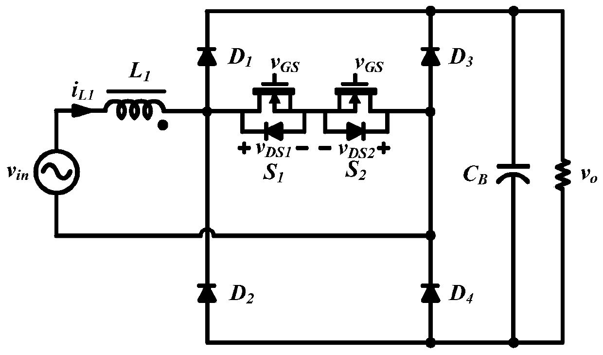
This control method needs to detect the input voltage V in The positive and negative half cycles of the input voltage, but near the zero-crossing moment of the input voltage, the input voltage amplitude is very small, and the signal sampled by the input voltage is easily disturbed by noise, so that the switch S 1 with S 2 Therefore, in order to avoid this situation, a certain size of dead time is often set when the input voltage power frequency is changed. The existence of this dead time will lead to a decrease in power factor

Method used


Image

  • Inductive current zero-crossing detection method of bridgeless power factor correction circuit
  • Inductive current zero-crossing detection method of bridgeless power factor correction circuit
  • Inductive current zero-crossing detection method of bridgeless power factor correction circuit

Examples


Embodiment Construction

[0049] The present invention will be further described below through specific embodiments in conjunction with the accompanying drawings. These embodiments are only used to illustrate the present invention, and are not intended to limit the protection scope of the present invention.

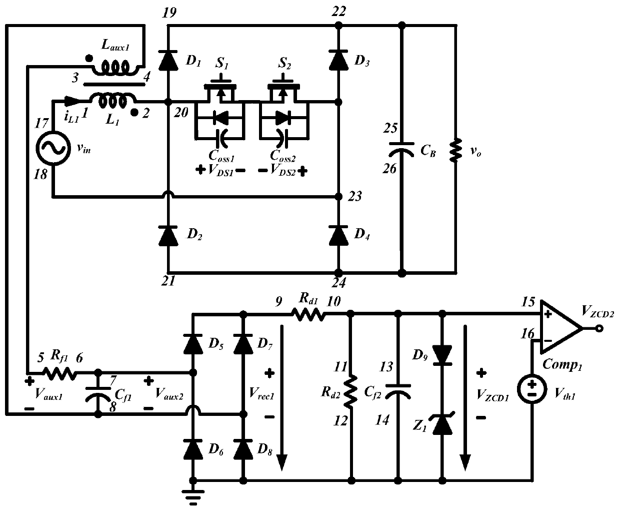
[0050] refer to image 3 The H-PFC circuit conceived according to the present invention does not need to detect the positive and negative half cycle of the input voltage power frequency and uses an auxiliary winding to realize the control of the critical continuous current mode. coupled to the inductor L 1 The auxiliary winding L aux1 The sensed voltage is the sense voltage V aux1 , due to the auxiliary winding L aux1 The voltage on V aux1 polarity and inductance L 1 The polarity of the voltage is reversed. Auxiliary winding L aux1 The voltage across V aux1 After being filtered by an RC, it is rectified by a rectifier bridge to obtain a rectified voltage V rec1 , detection voltage V rec1...


PUM


Abstract

The invention discloses an inductive current zero-crossing detection method for a bridgeless power factor correction circuit, and the circuit comprises an AC power supply, a first bridge arm, a secondbridge arm, a switch module group capable of enabling a current to flow in two directions, an inductor, an auxiliary winding, and a signal processing circuit. The detection method comprises: enablingthe auxiliary winding to generate a sensing voltage; the signal processing circuit generates an inductive current zero-crossing detection signal by using the sensing voltage; and when the inductive current zero-crossing point detection signal is a falling edge, the switch module capable of realizing bidirectional current flowing is conducted. According to the invention, an inductive current zero-crossing point detection signal is obtained by detecting the rectified voltage of the inductive current auxiliary winding, therefore, the H-PFC works in a critical conduction mode without detecting the positive and negative half cycles of the power frequency of the inductive current and the input voltage, and an inductive current zero-crossing detection signal irrelevant to the AC input voltage and the output load is obtained, so that the action of the switch module is accurate, the conduction loss is reduced, and the efficiency is improved.

Description

technical field [0001] The invention relates to the field of AC / DC conversion, in particular to an inductor current zero-crossing detection method capable of realizing a critical continuous current mode (Critical Continuous Current Mode) of a bridgeless power factor correction circuit (Bridgeless Power Factor Correction Circuit-PFC). Background technique [0002] Traditional boost (Boost) PFC circuits are divided into bridge PFC and bridgeless PFC. In the bridged PFC, the rectifier bridge loss is serious, and the bridgeless PFC omits the rectifier bridge structure compared with the bridged PFC, which reduces the on-state loss of a diode, so the bridgeless PFC is more conducive to improving the conversion efficiency of the entire switching power supply. H-Power Factor Corrector (H-PFC) is a bridgeless PFC topology suitable for medium and high power (such as figure 1 ). exist figure 1 , the bridgeless PFC accepts an input voltage of V in , generating an output voltage V o...

Claims


Application Information

Patent Timeline
Patent Type & Authority Applications(China)
IPC IPC(8): H02M1/42H02M7/219
CPCH02M1/4225H02M7/219H02M1/0009H02M1/0058Y02B70/10
Inventor 靳洋陈子健刘世超吴春瑜李阳吴新科马东
Owner SHANGHAI INST OF SPACE POWER SOURCES
Learn More