Electric linear motor and elevator

A linear motor, electric technology, used in electric components, elevators, elevators in buildings, etc., to improve safety

Inactive Publication Date: 2020-06-23
KONE CORP
View PDF0 Cites 0 Cited by
  • Summary
  • Abstract
  • Description
  • Claims
  • Application Information

AI Technical Summary

Problems solved by technology

Another challenge is that the mover tends to be tilted relative to the linear stator, i.e., turn clockwise or counterclockwise

Method used


Image

  • Electric linear motor and elevator
  • Electric linear motor and elevator
  • Electric linear motor and elevator

Examples


Embodiment Construction

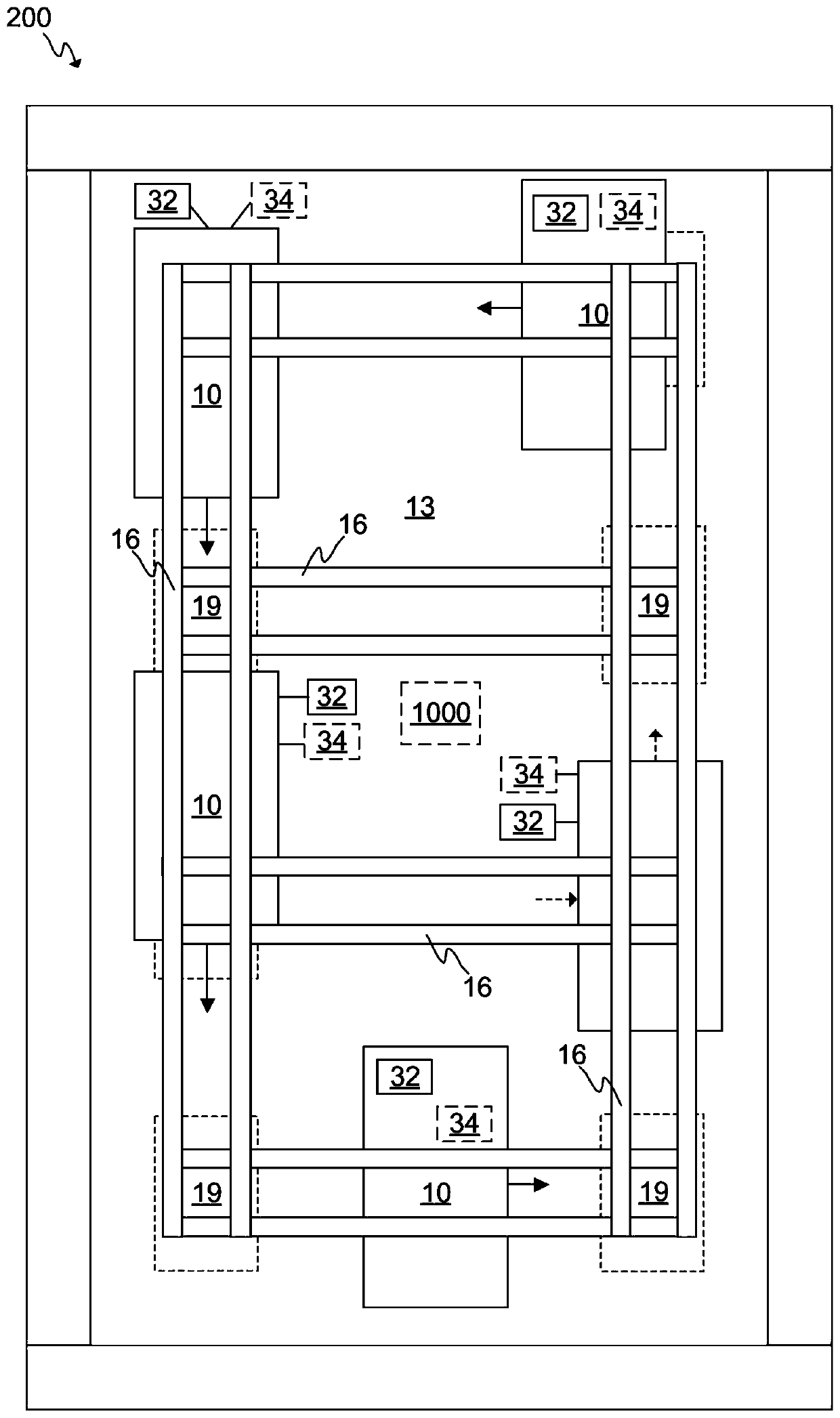
[0044] figure 1 An elevator 200 according to an embodiment of the invention is schematically shown. Elevator 200 may comprise at least one or more elevator cars 10 moving in elevator shaft 13 or elevator car hoistway 13 .

[0045] According to various embodiments, the elevator car 10 may comprise a number of electric drives 32, for example comprising one or several frequency converters or inverters. Additionally, one or more elevator cars 10 may comprise a first energy store 34, eg comprising one or more batteries, which are shown in dashed lines to indicate the optionality of the feature. This number of electric drives 32 can be used to operate movers ( figure 1 not shown in ), so that the car 10 moves in the elevator hoistway 13. There may also be other electrically operated equipment in the elevator car 10, such as lighting, doors, user interfaces, emergency rescue equipment, and the like. A number of electric drives 32 or further electric drive units such as inverters ...


PUM


Abstract

An electric linear motor (100) and an elevator (200) are presented. The electric linear motor (100) comprises a stator beam (16) comprising at least two stators rails (17), a number of movers (20) configured to move with respect to the stator beam (16), wherein each mover (20) comprises at least two motor units (22) which are configured to be arranged next to the stator beam (16) such that each one of the motor units (22) faces one of the stator rails (17), and each one of the at least two motor units (22) comprises at least two independently controllable motor subunits (25A, 25B, 25C, 25D) arranged consecutively with respect to a longitudinal direction (201) of the motor unit (22), wherein each of said motor subunits (25A, 25B, 25C, 25D) comprises windings (40) for generating a magnetic field to form magnetic coupling between the motor subunit (25A, 25B, 25C) and the respective stator rail (17).

Description

technical field [0001] The present invention generally relates to the technical field of electric linear motors. However, the invention relates particularly, but not exclusively, to electric linear motors for use in elevators. Background technique [0002] In some elevators, electric linear motors are used to move the elevator car between landing floors. Electric linear motors are especially suitable for elevators with very long elevator shafts, so-called high-rise elevators. The problem with high-rise elevators is that the weight of the hoisting ropes becomes so high that the ropes may not be able to support their own weight, let alone the weight of the elevator car. [0003] A typical electric linear motor is one that has a long linear stator equipped with controllable electromagnetic components such as coils for generating a magnetic field. The rotor or "mover" typically includes permanent magnets whose magnetic field causes the mover to move along the linear stator wh...

Claims


Application Information

Patent Timeline
Patent Type & Authority Applications(China)
IPC IPC(8): H02K41/02B66B11/04
CPCB66B11/0407H02K41/02H02K41/031H02K41/033B66B1/308B66B9/003B66B2201/30
Inventor T.科尔霍宁P.拉西纳S.苏尔-阿斯科拉
Owner KONE CORP
Why Eureka
Try Eureka