Continuous-circulation air-adsorption water intake device

An air water intake and circulation technology, applied in water supply installations, drinking water installations, buildings, etc., can solve the problems of power consumption, large volume of solar energy equipment, slow air intake of water intake devices, etc., to achieve great economic value and social benefits, guaranteeing Continuity and high efficiency, efficient adsorption/desorption effect

Active Publication Date: 2020-06-23
SHANGHAI MARITIME UNIVERSITY
View PDF6 Cites 2 Cited by
  • Summary
  • Abstract
  • Description
  • Claims
  • Application Information

AI Technical Summary

Problems solved by technology

[0003] Most of them have very high requirements on the ambient humidity. Generally, water can only be taken when the relative humidity is above 40%. However, due to the high air temperature and low relative humidity during the day, it is not conducive to the absorption of moisture in the air by hygroscopic materials. Therefore, most of them use nighttime adsorption. Water intake in the form of desorption during the day, that is, the water intake cycle is generally one day and night, which seriously restricts the continuity and efficiency of water intake by the device
[0004] Most of them operate at night, using electric energy, waste heat or stored solar energy to heat the hygroscopic material to desorb it. Although the desorption of the hygroscopic material at night is achieved, most of the solar equipment is bulky and complex in shape and structure, so the production cost is high. , The practical applicability is poor, or it does not conform to the environmental protection concept of green energy saving due to the consumption of other energy, making it difficult to popularize and use
[0005] Most of them rely on the form of natural convection to passively supply air to the water intake device. Therefore, the intake of the water intake device is slow, and the amount of moisture that the water intake device can absorb from the air per unit time is correspondingly small, which leads to a longer adsorption cycle of the water intake device. long, seriously restricting the water intake efficiency of the water intake device
Some also use air blower and other equipment to actively supply air to the water intake device to increase the air intake, but additional power consumption is required, and the heat generated by the blower and other equipment during operation will increase the temperature of the air, which is not conducive to subsequent adsorption

Method used


Image

  • Continuous-circulation air-adsorption water intake device
  • Continuous-circulation air-adsorption water intake device
  • Continuous-circulation air-adsorption water intake device

Examples


Embodiment Construction

[0060] The following is a further detailed description of a continuous circulation type adsorption air water intake device proposed by the present invention in conjunction with the accompanying drawings and specific embodiments. The advantages and features of the present invention will become apparent from the following description and claims. It should be noted that, the accompanying drawings are all in a very simplified form and use imprecise ratios, and are only used to facilitate and clearly assist the purpose of explaining the embodiments of the present invention.

[0061] like figure 1 As shown, the embodiment of the present invention provides a continuous circulation type adsorption air water intake device, which includes:

[0062] Air collection system 1, which is used to collect air and introduce it into the air collection system;

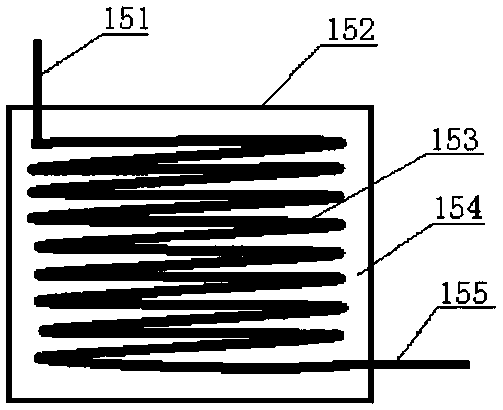
[0063] The first cooling system 15, which is connected to the gas collection system 1 pipeline, the first cooling system 15 is located ...


PUM


Abstract

The invention discloses a continuous-circulation air-adsorption water intake device which comprises an air collection system, a first cooling system, at least one adsorption component, a second cooling system and at least one wind-power magneto-electricity system. The first cooling system and the second cooling system disclosed by the invention are located underground, and air is cooled by low temperature underground, so that adverse influences of high air temperature in the daytime on normal adsorption of the water intake device are avoided; and in addition, electric energy is generated by wind energy, and the water intake device can run normally at night, so that continuity and high efficiency of the water intake device are realized.

Description

technical field [0001] The invention relates to the technical field of fresh water acquisition, in particular to an adsorption type air water intake device which utilizes underground low temperature and wind energy for continuous circulation. Background technique [0002] With the deteriorating environment, water shortage has become a global problem. Due to the gas, liquid and solid three-state transformation of water on the earth and the mass conservation of water, the atmosphere is the intermediate link of the three-state transformation cycle, so obtaining water from the air has become an effective way to solve the shortage of water resources. At present, relevant researchers have proposed a variety of air water intake devices, most of which use the adsorption / desorption method to obtain fresh water from the air. Directly irradiate or rely on other energy such as electric energy to heat the hygroscopic material to desorb at high temperature, and finally condense the desor...

Claims


Application Information

Patent Timeline
Patent Type & Authority Applications(China)
IPC IPC(8): E03B3/28
CPCE03B3/28
Inventor 张功慧冯道伦孙化栋
Owner SHANGHAI MARITIME UNIVERSITY
Why Eureka
Try Eureka