
Double-station board machining center

A plate processing, double-station technology, applied in the direction of metal processing, metal processing equipment, metal processing machinery parts, etc., can solve the limitation of the working efficiency of the machining center, can only process inclined holes with a fixed angle, poor applicability of equipment, etc. problems, to achieve the effect of expanding applicability, improving overall processing efficiency, and reducing processing waiting time

Active Publication Date: 2020-06-23
HEFEI JINDIAO DIGITAL CONTROL EQUIP
View PDF10 Cites 0 Cited by
  • Summary
  • Abstract
  • Description
  • Claims
  • Application Information

AI Technical Summary

Problems solved by technology

[0002] At present, the sheet metal processing center is usually set up with a single station. During the loading and unloading process of the sheet metal and the positioning and clamping process, the spindle cannot perform processing work, which limits the improvement of the working efficiency of the processing center, especially in some areas where the degree of automation is low and manual loading and unloading is required. Material, manual positioning and clamping processing equipment, the limitations of this loading and unloading and clamping method on processing efficiency will be more prominent and obvious, and the current mainstream plate processing equipment on the market is usually difficult to process inclined holes with inclination angles, or Can only process oblique holes with a certain fixed angle, and the applicability of the equipment is poor

Method used


Image

  • Double-station board machining center
  • Double-station board machining center
  • Double-station board machining center

Examples

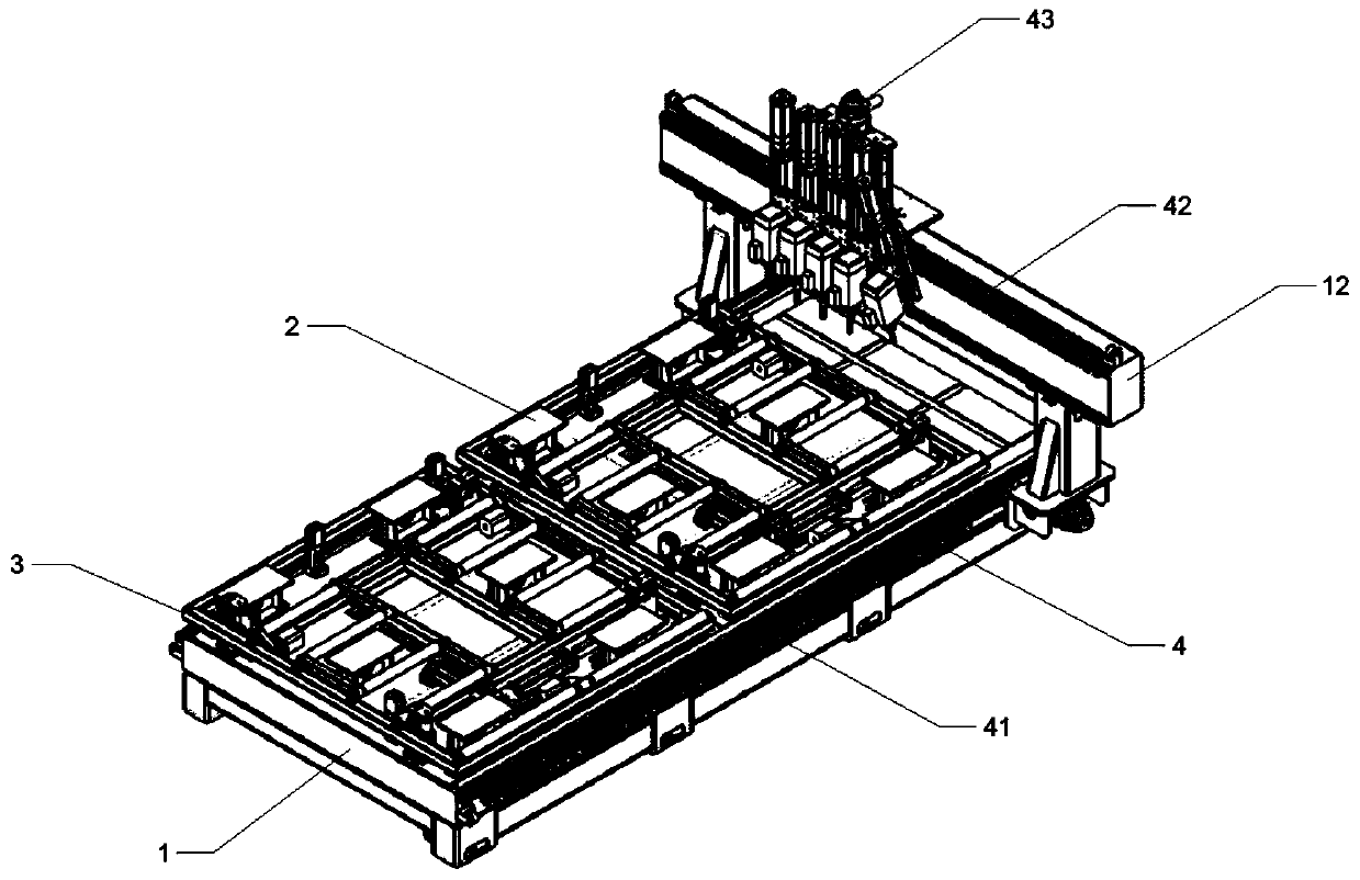
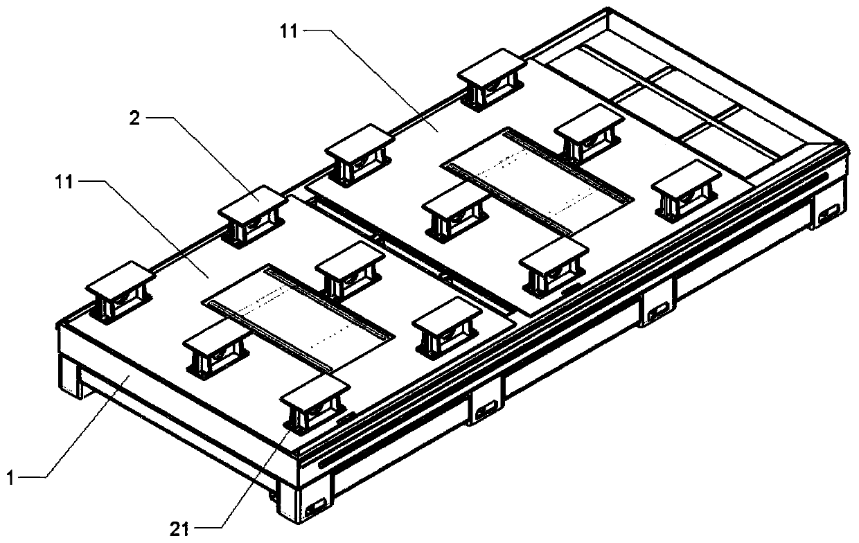
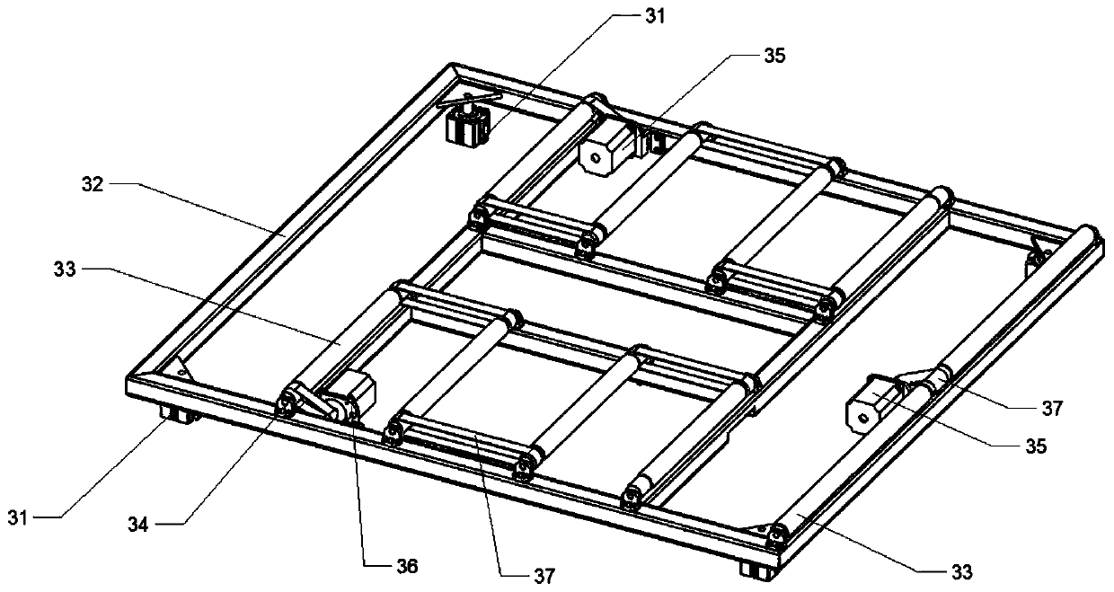

Embodiment Construction

[0025] In order to make the technical means, creative features, goals and effects achieved by the present invention easy to understand, the present invention will be further described below in conjunction with specific embodiments.

[0026] like Figure 1-12As shown, a double-station plate processing center includes a base 1, a beam 12, a support platform 2, a roller conveyor 3, a three-coordinate walking assembly 4, a spindle system 5, a spindle inclined hole system 6, and X-direction positioning Component 7, Y-direction positioning and pressing component 8, the base 1 is provided with a plurality of processing stations 11, and the upper surface of the processing station 11 is provided with a plurality of independent supporting platforms 21, and the processing stations 11 The middle part of the upper surface of the upper surface is provided with a roller conveying platform 3, and the processing station 11 is respectively provided with an X-direction positioning assembly 7 and...


PUM


Abstract

The invention discloses a double-station board machining center. The double-station board machining center comprises a base, a beam and further comprises a three-coordinate traveling assembly; the base is provided with a plurality of machining stations; supporting platforms are arranged on the upper surfaces of the machining stations; drum conveying tables are arranged at the middle parts of the upper surfaces of the machining stations; X-directional positioning assemblies and Y-directional positioning compressing assemblies are respectively arranged on the machining stations; the three-coordinate traveling assembly comprises Y-axis traveling assemblies; the Y-axis traveling assemblies are mounted on both sides of the base; the beam is erected at the upper ends of the Y-axis traveling assemblies; an X-axis traveling assembly is arranged on the beam; a Z-axis traveling assembly is mounted on the X-axis traveling assembly; a spindle system is arranged on the Z-axis traveling assembly; and a spindle inclined hole system is arranged on the spindle system. According to the invention, by disposing a plurality of machining stations, machining waiting time of the three-coordinate travelingassembly is reduced; and meanwhile, the spindle inclined hole system is arranged, so that overall machining efficiency of machining boards is improved, and various angles of inclined holes can also be machined.

Description

technical field [0001] The invention relates to the field of mechanical processing, in particular to a double-station plate processing center. Background technique [0002] At present, the sheet metal processing center is usually set up with a single station. During the loading and unloading process of the sheet metal and the positioning and clamping process, the spindle cannot perform processing work, which limits the improvement of the working efficiency of the processing center, especially in some areas where the degree of automation is low and manual loading and unloading is required. Material, manual positioning and clamping processing equipment, the limitations of this loading and unloading and clamping method on processing efficiency will be more prominent and obvious, and the current mainstream plate processing equipment on the market is usually difficult to process inclined holes with inclination angles, or Only oblique holes with a certain fixed angle can be proces...

Claims


Application Information

Patent Timeline
IPC IPC(8): B23B47/00B23Q3/06B23Q7/00B23Q7/05B23Q5/34B23Q15/26
CPCB23B47/00B23Q3/06B23Q5/34B23Q7/005B23Q7/05B23Q15/26
Inventor 高家迁
Owner HEFEI JINDIAO DIGITAL CONTROL EQUIP
Learn More