
A continuous frying device for hollow crisp production

A hollow and deep-fried box technology, applied in the direction of oil/fat baking, etc., can solve the problems of manpower consumption and low efficiency, and achieve the effects of improving production efficiency, simplifying the mechanism, and shortening the window period

Active Publication Date: 2021-08-06
ANHUI PANPAN FOOD CO LTD
View PDF0 Cites 0 Cited by
  • Summary
  • Abstract
  • Description
  • Claims
  • Application Information

AI Technical Summary

Problems solved by technology

[0004] The purpose of the present invention is to solve the problems of labor-intensive and low efficiency in the prior art, and propose a continuous frying device for hollow crisp production

Method used


Image

  • A continuous frying device for hollow crisp production
  • A continuous frying device for hollow crisp production
  • A continuous frying device for hollow crisp production

Examples


Embodiment 1

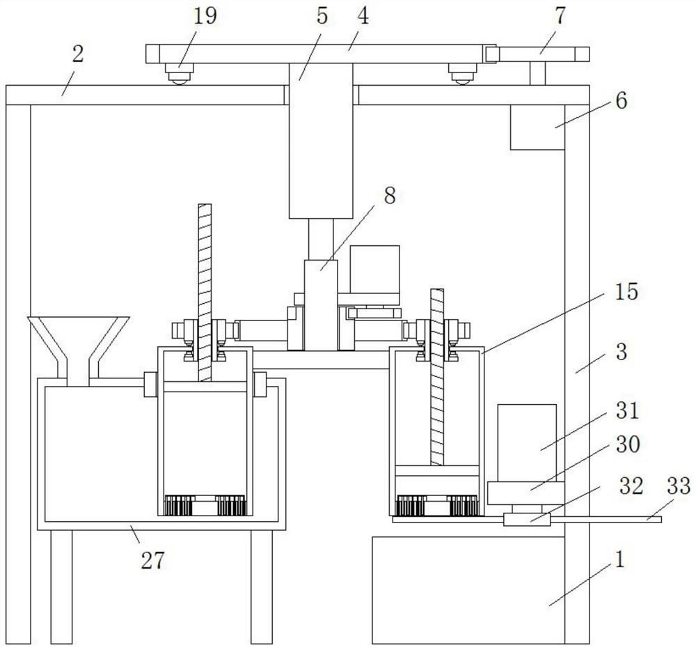
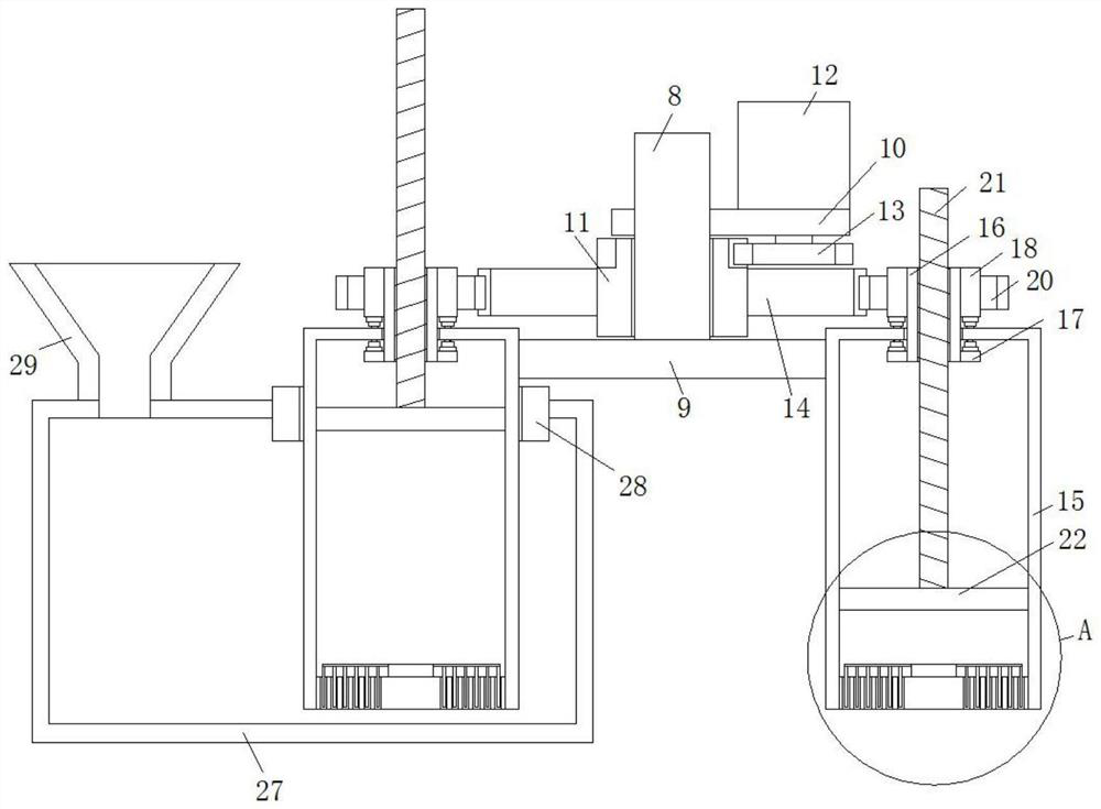
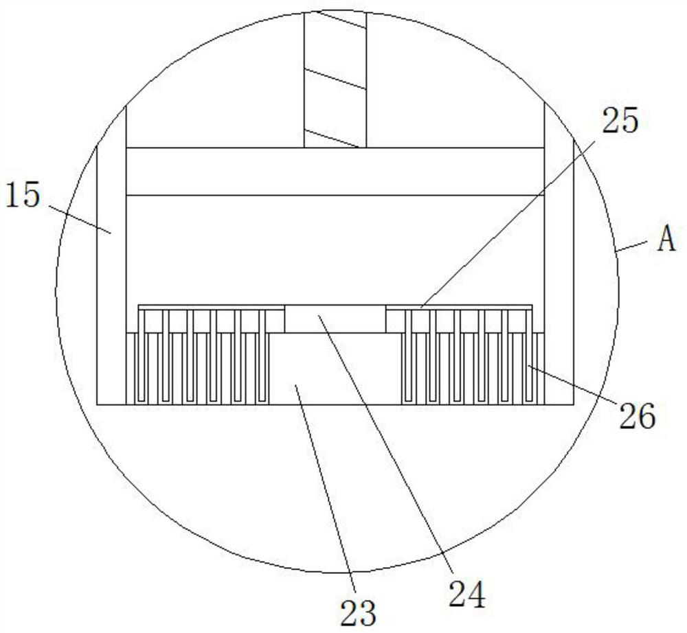
[0022] refer to Figure 1-4 , a continuous frying device for hollow brittle production, comprising a frying box 1, the top of the frying box 1 is provided with a feeding mechanism, the feeding mechanism includes a top plate 2, and the four corners of the bottom side of the top plate 2 are fixedly connected with legs 3, The vertical top of the top plate 2 is provided with an installation disc 4, and the bottom side of the installation disc 4 is fixed with a cylinder 5 by bolts. The body of the top plate 2 is provided with a vertical through hole, and the cylinder 5 passes through the vertical through hole. However, one side of the top plate 2 is fixedly installed with a motor 6 by bolts, and the output shaft of the motor 6 is connected with a gear 7 behind, and the vertical side of the installation disc 4 is provided with a tooth groove and meshed with the gear 7. , the output rod of the cylinder 5 is fixedly connected with the central axis column 8, the bottom end of the centr...

Embodiment 2

[0025] Such as Figure 1-4 As shown, this embodiment is basically the same as Embodiment 1. Preferably, the mounting ring 10 is fixedly connected to the central axis column 8, the collar 11 is rotatably set on the outside of the central axis column 8, and the collar 11 is located on the central axis plate 9 and mounting ring 10.

[0026] In this embodiment, while the installation ring 10 is used as the installation base of the second motor 12 , it also defines the vertical height position of the collar 11 relative to the central axis column 8 .

Embodiment 3

[0028] Such as Figure 1-4 As shown, this embodiment is basically the same as Embodiment 1. Preferably, the top side of the scraper 33 is in sliding contact with the bottom side of the bottom template 23 , and the scraper 33 is located vertically above the fryer 1 .

[0029] In this embodiment, through the setting of the scraper 28, the material falling from the retrieving box 15 is cut to form a hollow brittle section.


PUM


Abstract

The invention discloses a continuous frying device for hollow brittle production, which comprises a frying box, a feeding mechanism is arranged on the top of the frying box, the feeding mechanism includes a top plate, and the four corners of the bottom side of the top plate are fixedly connected with The vertical top of the support foot, the top plate, is provided with an installation disc, and the bottom side of the installation disc is fixed with a cylinder by bolts, and the body of the top plate is provided with a vertical through hole, and the cylinder passes through the vertical through hole. Through the inside, one side of the top plate is fixed with a motor 1 by bolts, and the output shaft of the motor 1 is connected with a gear 1, and the vertical side of the installation disc is provided with a tooth groove 1 and meshed with the gear 1, and the cylinder The output rod is fixedly connected with a central axis column, the bottom end of the central axis column is fixedly connected with a central axis plate, and the outer side of the cylinder of the central axis column is provided with a mounting ring and a collar. The invention improves the production efficiency, has a simplified mechanism and a reasonable design, and satisfies the use requirements of people in production and life.

Description

technical field [0001] The invention relates to the technical field of food processing equipment, in particular to a continuous frying device for hollow brittle production. Background technique [0002] Fried food is loved by many adults and children because of its crispy taste, tangy aroma, and ability to increase appetite. [0003] The existing frying device for hollow brittle production uses a single-tube retrieving box to take and discharge materials, or manually loads materials, which is time-consuming and laborious, and the empty window period of the frying equipment is long. The efficiency is low, and it cannot meet the needs of people in production and life. Contents of the invention [0004] The purpose of the present invention is to solve the problems of labor-consuming and low efficiency in the prior art, and propose a continuous frying device for hollow crisp production. [0005] In order to achieve the above object, the present invention adopts the following...

Claims


Application Information

Patent Timeline
Patent Type & Authority Patents(China)
IPC IPC(8): A21B5/08
CPCA21B5/08
Inventor 蔡镕骏蔡丕鹏蔡金钗步显勇蔡金垵谢艳
Owner ANHUI PANPAN FOOD CO LTD
Learn More