
Wind turbine blade aerodynamic structure coupling design method

A technique for coupling design, wind turbine blades

Active Publication Date: 2020-06-19
GUANGDONG MINGYANG WIND POWER IND GRP CO LTD
View PDF3 Cites 8 Cited by
  • Summary
  • Abstract
  • Description
  • Claims
  • Application Information

AI Technical Summary

Problems solved by technology

The power generation, structural strength, and stiffness of the blades are designed using a variety of software. The design process requires repeated iterations, and the software calculation time is relatively long. New blades require a long development cycle.

Method used

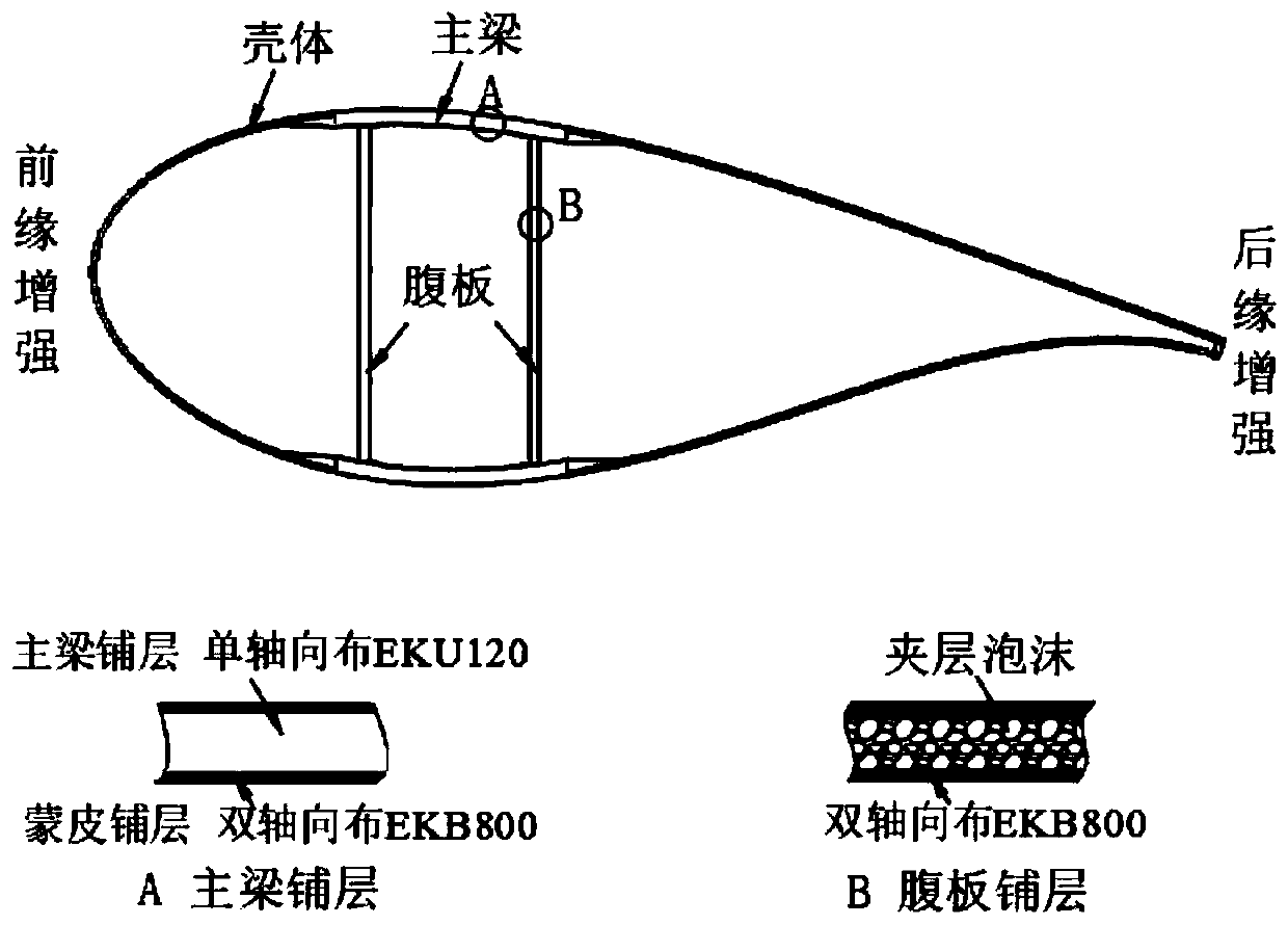
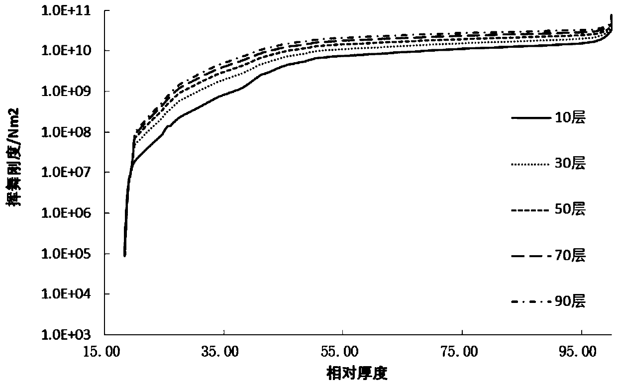
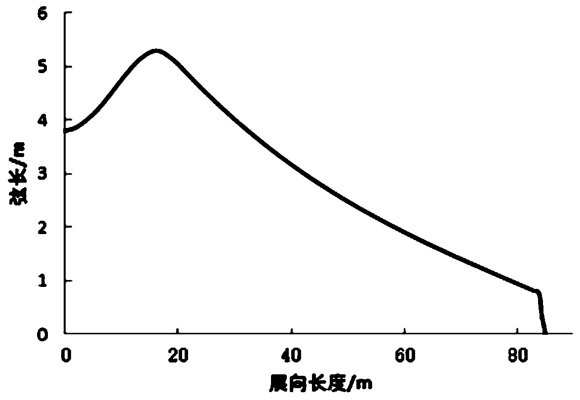

Image

  • Wind turbine blade aerodynamic structure coupling design method
  • Wind turbine blade aerodynamic structure coupling design method
  • Wind turbine blade aerodynamic structure coupling design method

Examples


Embodiment Construction

[0044] The present invention will be further described below in conjunction with specific examples.

[0045] The specific conditions of the coupling design method for the aerodynamic structure of wind power blades provided in this embodiment are as follows:

[0046] 1) Input design parameters

[0047] Unit-related parameters: input unit rated power, maximum speed, unit loss, average wind speed, Weibull distribution curve shape parameter k, axial thrust limit value, maximum allowable waving deformation, wind energy utilization coefficient Cp design value.

[0048] Geometric design parameters: maximum chord length change range and change step size, blade root chord length change range and change step size, spanwise position range and change step size corresponding to the maximum chord length, chord length range and change step size near the blade tip Length, thickness design parameters, root to tip spar layup function distribution.

[0049] 2) Blade geometric parameter design

...


PUM


Abstract

The invention discloses a wind turbine blade aerodynamic structure coupling design method which comprises the following steps: 1) inputting design parameters including unit related parameters and geometric design parameters; 2) blade geometric parameter design: generating wind power blade chord length distribution, torsion angle distribution and airfoil profile relative thickness distribution through main parameterization; 3) blade aerodynamic load calculation, (4) blade rigidity calculation based on database interpolation, (5) blade waving deformation calculation and (6) data screening and determination of a final design plant. The design, research and development efficiency of the wind turbine blade can be greatly improved, the number of iterations in blade design is reduced, and finallyblade loads and blade mass are reduced.

Description

technical field [0001] The invention relates to the technical field of renewable new energy wind power blades, in particular to an aerodynamic structure coupling design method for wind power blades. Background technique [0002] With the rapid increase of wind power generation power, wind power blades are rapidly developing towards large-scale, lightweight and intelligent. Due to the mutually restrictive relationship among aerodynamics, structure, and blade cost, that is, the greater the blade chord length, the greater the thickness, and the more layers of the main beam, the greater the stiffness of the blade and the stronger the bearing capacity. However, the corresponding weight of the blade is greater, and the cost is higher. [0003] In terms of aerodynamic design, the researchers used the annual power generation and cost of electricity as the objective function, combined with genetic algorithm and particle swarm algorithm to design the blades. Taking the annual power ...

Claims


Application Information

Patent Timeline
Patent Type & Authority Applications(China)
IPC IPC(8): G06F30/10G06F30/17F03D1/06G06F119/14
CPCF03D1/0633F03D1/0675Y02E10/72
Inventor 刘峰高猛孙松峰陈文光李军向
Owner GUANGDONG MINGYANG WIND POWER IND GRP CO LTD
Learn More