
APD bias voltage compensation circuit, compensation method and system, storage medium and control terminal

A technology for controlling terminals and bias circuits, applied in control/regulating systems, regulating electrical variables, instruments, etc., can solve problems such as inability to meet compensation, and inability to perform normal detection, and achieve the effect of reducing workload and labor costs

Pending Publication Date: 2020-06-19
KEENON ROBOTICS CO LTD
View PDF0 Cites 4 Cited by
  • Summary
  • Abstract
  • Description
  • Claims
  • Application Information

AI Technical Summary

Problems solved by technology

[0004] In the prior art, most APD detection instruments are based on optical fiber communication APDs for bias detection, and their instruments can only detect APD bias voltages within 0-70V, while APD bias voltages used in laser ranging and lidar Between 80V-300V, so normal detection cannot be performed
In addition, the existing detection instruments can only detect the APD bias voltage at the current temperature, which cannot satisfy the compensation under a wide range of temperatures

Method used


Image

  • APD bias voltage compensation circuit, compensation method and system, storage medium and control terminal
  • APD bias voltage compensation circuit, compensation method and system, storage medium and control terminal
  • APD bias voltage compensation circuit, compensation method and system, storage medium and control terminal

Examples


Embodiment Construction

[0048] Embodiments of the present invention are described below through specific examples, and those skilled in the art can easily understand other advantages and effects of the present invention from the content disclosed in this specification. The present invention can also be implemented or applied through other different specific implementation modes, and various modifications or changes can be made to the details in this specification based on different viewpoints and applications without departing from the spirit of the present invention. It should be noted that, in the case of no conflict, the following embodiments and features in the embodiments can be combined with each other.

[0049] It should be noted that the diagrams provided in the following embodiments are only schematically illustrating the basic ideas of the present invention, and only the components related to the present invention are shown in the diagrams rather than the number, shape and shape of the compo...


PUM


Abstract

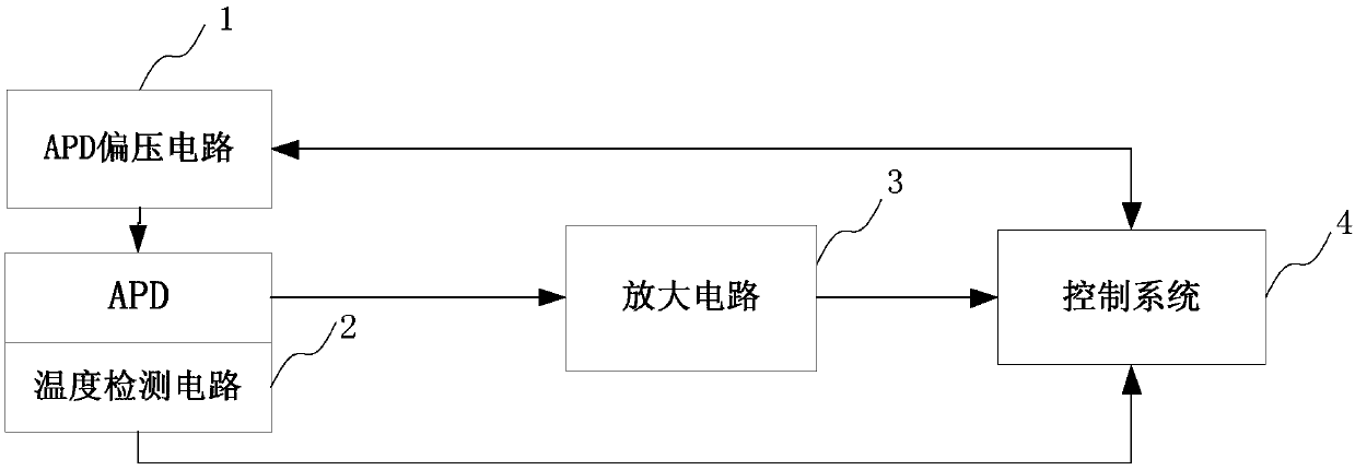
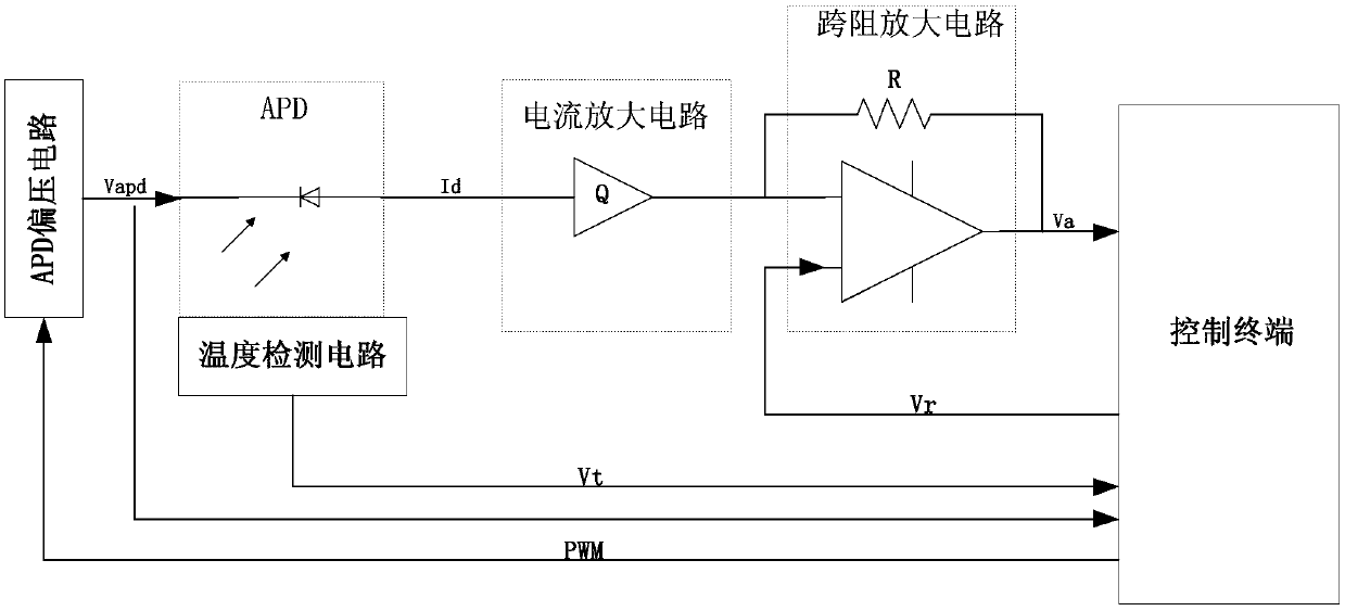
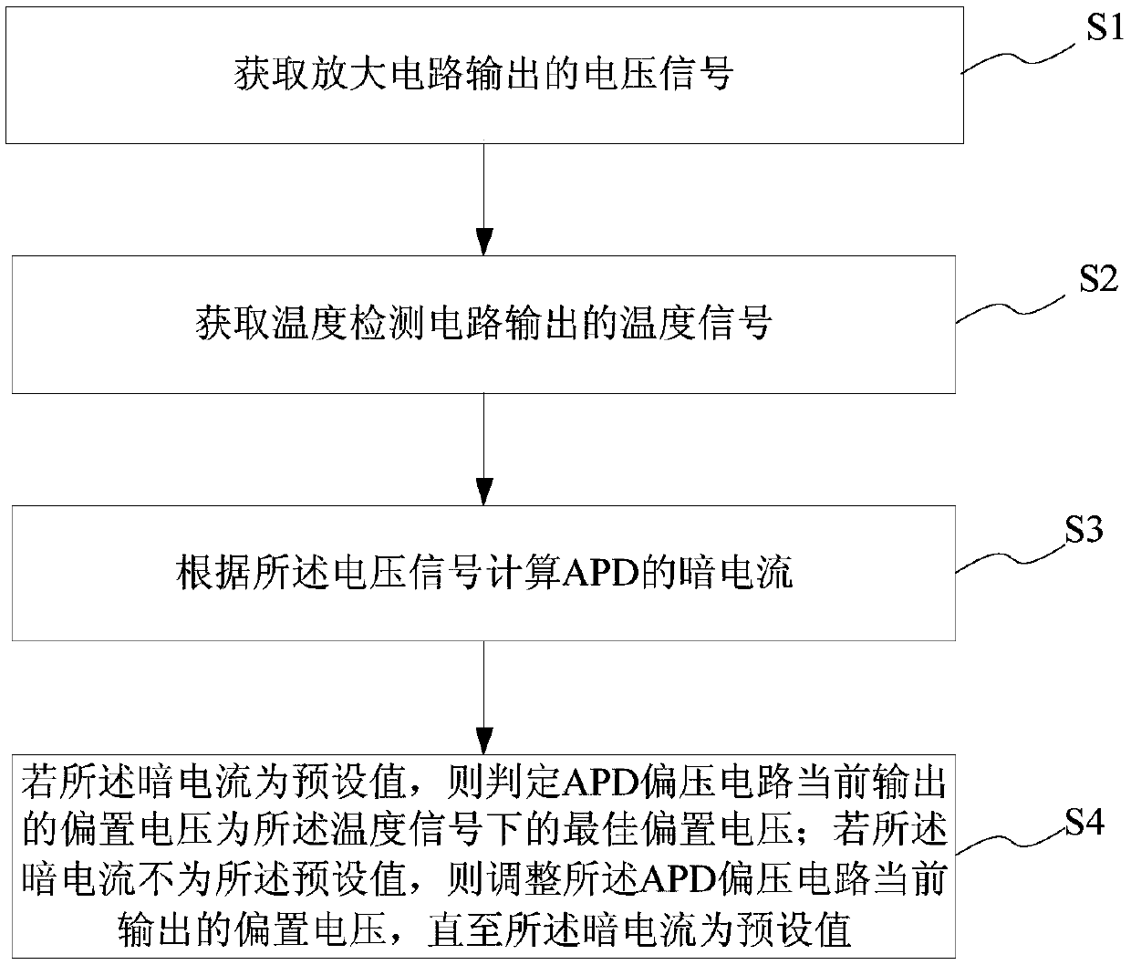
The invention provides an APD bias voltage compensation circuit, an APD bias voltage compensation method and system, a storage medium and a control terminal. The APD bias voltage compensation circuitcomprises an APD bias voltage circuit, a temperature detection circuit, an amplification circuit and the control terminal. The APD bias circuit provides bias voltage for the APD under the control of the control terminal; the amplifying circuit amplifies dark current generated by the APD into a voltage signal and sends the voltage signal to the control terminal; the temperature detection circuit collects temperature information of the APD and sends the temperature information to the control terminal; and the control terminal adjusts the bias voltage according to the voltage signal so as to enable the dark current to be a preset value, and adjusts the bias voltage according to the temperature information so as to enable the dark current to be kept at the preset value when the temperature information changes. According to the APD bias voltage compensation circuit, the compensation method and system, the storage medium and the control terminal, the optimal gain state of the APD at different temperatures can be obtained.

Description

technical field [0001] The present invention relates to a compensation circuit, in particular to an avalanche photodiode (Avalanche PhotoDiode, APD) bias voltage compensation circuit, compensation method and system, storage medium and control terminal. Background technique [0002] APD is a photosensitive element used in laser communication. After the reverse bias is added to the P-N junction of the photodiode made of silicon or germanium, the incident light will be absorbed by the P-N junction to form a photocurrent; increasing the reverse bias will produce "avalanche" ( That is, the photocurrent exponentially increases), so this kind of diode is called an avalanche photodiode. [0003] With the rapid application and development of laser ranging and lidar, it is very important to achieve rapid mass production. In the mass production process of laser ranging and lidar, the consistency of APD is the biggest problem. The APDs provided by APD manufacturers all have a wide ra...

Claims


Application Information

Patent Timeline
IPC IPC(8): G05F1/567
CPCG05F1/567
Inventor 冉银春周驰金超唐旋来李通
Owner KEENON ROBOTICS CO LTD
Learn More