Electric car parallel flow condenser core

A technology of parallel flow and condenser, applied in the direction of evaporator/condenser, refrigerator, refrigeration components, etc., can solve the problems of inconvenient replacement, core damage, etc., and achieve the effect of improving service life and quality

Inactive Publication Date: 2020-06-19
上海晟铭汽车配件有限公司
View PDF0 Cites 1 Cited by
  • Summary
  • Abstract
  • Description
  • Claims
  • Application Information

AI Technical Summary

Problems solved by technology

[0002] The existing electric vehicle parallel flow condenser core, because the shape of the parallel flow condenser core is relatively flat, in order to ensure that the condensed gas circulates evenly in the core, the installation requirements for the core are relatively high. If the core is installed tilted, The condensed gas will flow empty or even reflux. Secondly, the condensed gas contains a lot of water and impurities. If it is not filtered in time, it will cause damage to the core body. Most of the existing core bodies are used for this task by drying bottles. However, when the filter structure inside the drying bottle is saturated, it is not easy to replace. Therefore, we propose to avoid the uneven flow of condensed gas in the inner coil in the later stage due to the installation tilt, so as to prevent the condensed air flow from emptying or even backflow, which is convenient for users to replace. to solve the above problems

Method used


Image

  • Electric car parallel flow condenser core
  • Electric car parallel flow condenser core
  • Electric car parallel flow condenser core

Examples


Embodiment Construction

[0020] The specific implementation manner of the present invention will be described in detail below in conjunction with the accompanying drawings.

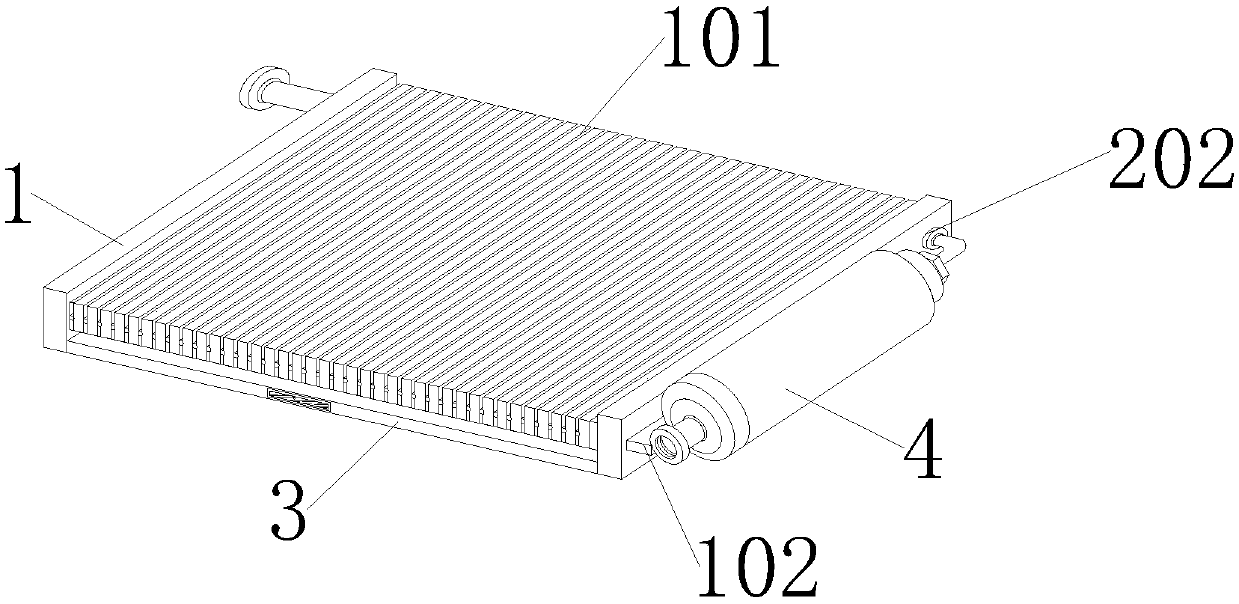
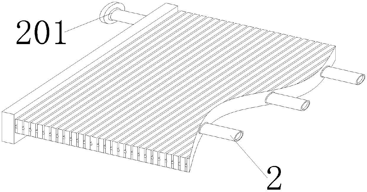
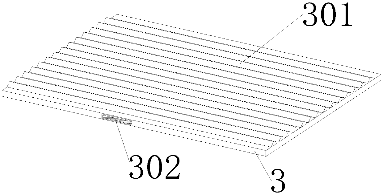
[0021] see Figure 1-5 As shown, a parallel-flow condenser core for an electric vehicle, the parallel-flow condenser core for an electric vehicle includes a support plate 1 and a backing plate 3, the number of support plates 1 is two, and the inner wall of the support plate 1 is between the left and right sides The backing plate 3 is welded below, and several fins 101 are welded between the support plates 1 and above the backing plate 3, and the inner coil 2 is installed inside the fins 101, and the right rear end of the inner coil 2 is set through the The support plate 1 on the right has an interface 202 on the right rear end of the inner coil 2, the left rear end of the inner coil 2 runs through the left support plate 1, and the left rear end of the inner coil 2 has a At the outlet 201, at least ten top blocks 301 are uniforml...


PUM


Abstract

The invention provides an electric car parallel flow condenser core and relates to the technical field of condensers. A base plate is welded between the bottom ends of supporting plates. A plurality of fins are welded to the location, located on the base plate, between the supporting plates. An inner coil pipe is arranged inside the fins in a penetration mode. The right end of the right side of the inner coil pipe penetrates through the supporting plate on the right side. The rear end of the right side of the inner coil pipe is provided with a connector. The rear end of the left side of the inner coil pipe penetrates through the supporting plate on the left side. The rear end of the left side of the inner coil pipe is provided with an outlet. The top end of the base plate is uniformly andfixedly connected with at least ten top blocks. A drying bottle is welded to the right side of the supporting plate on the right side through soldering lugs. The upper and lower ends of the drying bottle are both provided with straight slideways, and the flow non-uniformity of condensed gas in the inner coil pipe during the later period due to inclined installation can be avoided. A user can replace the electric car parallel flow condenser core conveniently. The problems that condensed gas is prone to flow empty even backflow and a filter structure in the drying bottle is inconvenient to replace during saturation are solved.

Description

technical field [0001] The invention relates to the technical field of condensers, in particular to a parallel-flow condenser core for electric vehicles. Background technique [0002] The existing electric vehicle parallel flow condenser core, because the shape of the parallel flow condenser core is relatively flat, in order to ensure that the condensed gas circulates evenly in the core, the installation requirements for the core are relatively high. If the core is installed tilted, The condensed gas will flow empty or even reflux. Secondly, the condensed gas contains a lot of water and impurities. If it is not filtered in time, it will cause damage to the core body. Most of the existing core bodies are used for this task by drying bottles. However, when the filter structure inside the drying bottle is saturated, it is not easy to replace. Therefore, we propose to avoid the uneven flow of condensed gas in the inner coil in the later stage due to the installation tilt, so as ...

Claims


Application Information

Patent Timeline
Patent Type & Authority Applications(China)
IPC IPC(8): F25B39/04F28F1/32F28F9/007F28F17/00F28F19/01F28F27/00
CPCF25B39/04F25B2339/047F28F1/32F28F9/007F28F17/00F28F19/01F28F27/00
Inventor 陶峻霞
Owner 上海晟铭汽车配件有限公司
Why Eureka
Try Eureka