
A New Ventilation Device Used in Buildings

A ventilation device, a new type of technology, is applied in the direction of ventilation system, space heating and ventilation, space heating and ventilation details, etc. It can solve the problems of difficult ventilation and air humidity that cannot be adjusted, so as to achieve convenient regulation, improve ventilation capacity, The effect of improving the suction power

Inactive Publication Date: 2021-06-04
ZHONGYUAN ENGINEERING COLLEGE
View PDF6 Cites 0 Cited by
  • Summary
  • Abstract
  • Description
  • Claims
  • Application Information

AI Technical Summary

Problems solved by technology

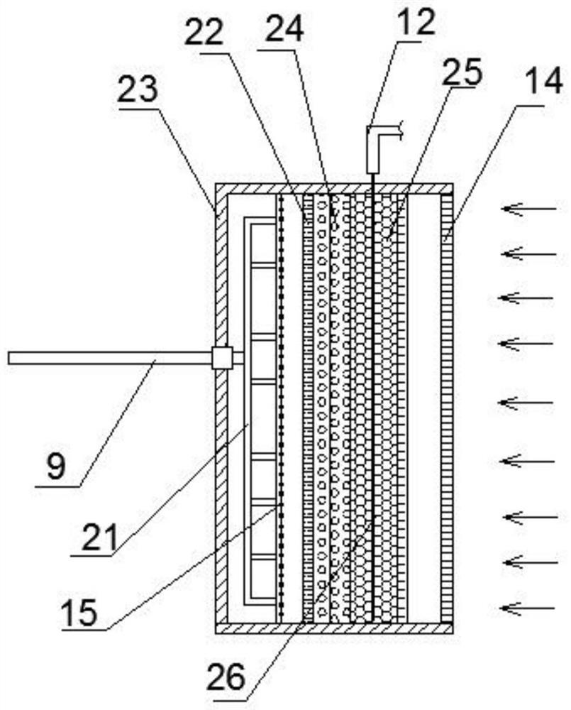
[0002] In building ventilation, fans are generally used to introduce external air into the building. Although this method is simple, one problem is that the humidity of the introduced air cannot be adjusted during ventilation. Another problem is that the current Ventilation facilities are generally arranged in the ventilation shaft. For the ventilation facilities in the ventilation shaft, it can only realize the ventilation of the basement and the surrounding positions connected with the ventilation shaft of the building. For relatively closed areas in the building, such as toilets, It is difficult to achieve ventilation in corridors, etc. Therefore, how to design a ventilation device is very important for the ventilation of buildings

Method used


Image

  • A New Ventilation Device Used in Buildings
  • A New Ventilation Device Used in Buildings
  • A New Ventilation Device Used in Buildings

Examples


Embodiment Construction

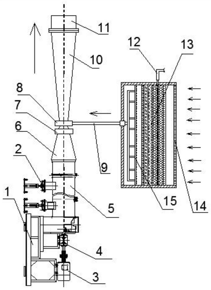
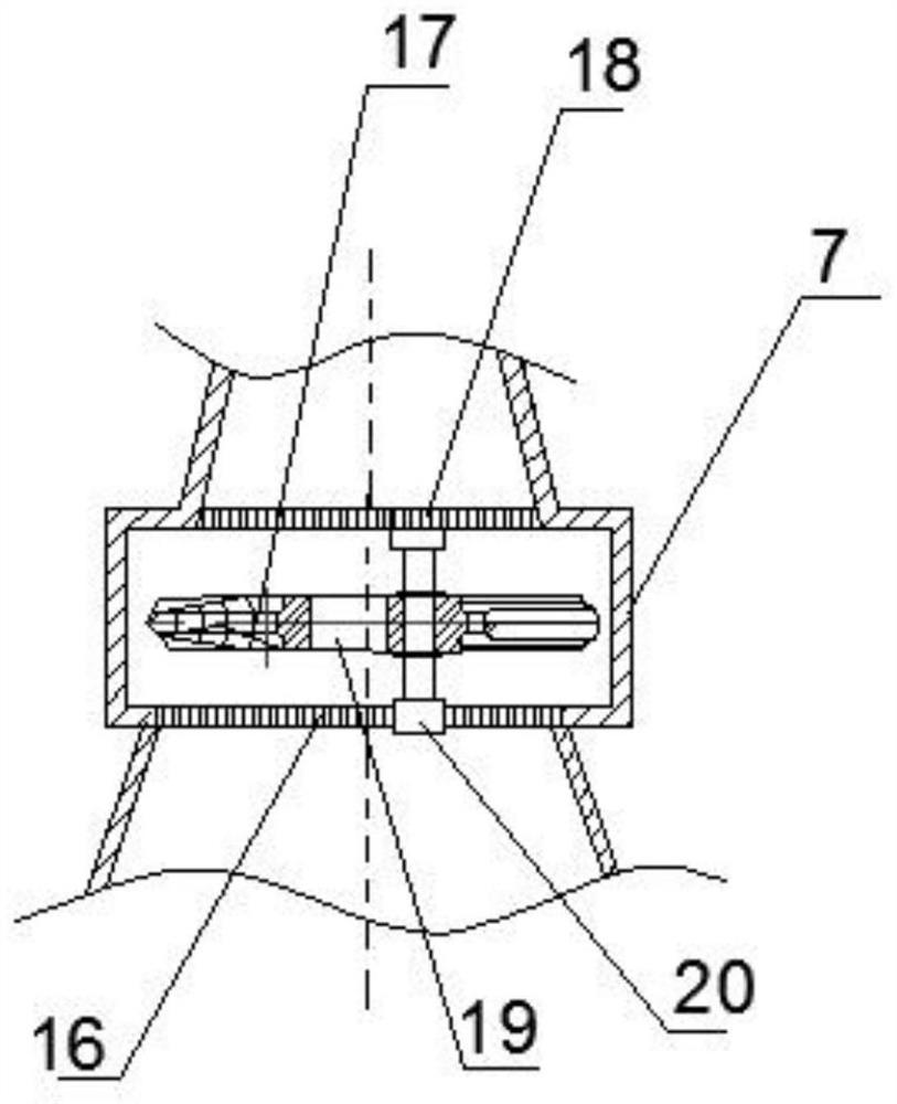
[0023] see Figure 1~4 , in an embodiment of the present invention, a novel ventilation device for buildings, including a mounting base 1, a ventilation fan unit, a lower ventilator 5, an upper ventilator 11, a lower conical pipe 6, an upper conical pipe 10, and a suction pipe 9 and the air flow control mechanism 7, wherein the ventilation fan unit is installed on the mounting base, the output end of the ventilation fan unit is connected to the lower ventilator, and the upper end of the lower ventilator is connected to the lower cone Pipe 6, the upper end of the lower conical pipe 6 is connected with the upper ventilator through the upper conical pipe, it is characterized in that the upper small end of the lower conical pipe 6 is connected with the lower small end of the upper conical pipe 10 It is arranged close to the connection, and a connection suction cup 8 is connected between the lower conical pipe 6 and the upper conical pipe 10, and the suction pipe 9 is connected to ...


PUM


Abstract

The invention discloses a new type of ventilation device for buildings. The upper small end of the lower conical pipe of the present invention is arranged in close connection with the lower small end of the upper conical pipe, and a connecting suction cup is arranged between the lower conical pipe and the upper conical pipe. In this way, after the airflow of the lower conical tube flows to the upper conical tube, due to the contraction and diffusion of the conical tube, a certain negative pressure can be formed at the connection with the suction cup, and this negative pressure will make the suction tube suck At the same time, the airflow control mechanism of the present invention can make the flow velocity of the airflow flowing from the lower conical pipe to the upper conical pipe continuously present periodic or non-periodic changes, which can effectively make the suction airflow in the suction pipe also at During the change, it not only facilitates the change of the air flow during humidity adjustment, but also ensures that water molecules escape from the humidity adjustment mechanism, and facilitates the suction of the suction pipe, improving the suction capacity of the suction pipe.

Description

technical field [0001] The invention relates to a building ventilation device, in particular to a novel ventilation device for buildings. Background technique [0002] In building ventilation, fans are generally used to introduce external air into the building. Although this method is simple, one problem is that the humidity of the introduced air cannot be adjusted during ventilation. Another problem is that the current Ventilation facilities are generally arranged in the ventilation shaft. For the ventilation facilities in the ventilation shaft, it can only realize the ventilation of the basement and the surrounding positions connected with the ventilation shaft of the building. For relatively closed areas in the building, such as toilets, It is difficult to achieve ventilation in corridors, etc. Therefore, how to design a ventilation device is very important for the ventilation of buildings. [0003] Therefore, the present invention provides a novel ventilation device for...

Claims


Application Information

Patent Timeline
Patent Type & Authority Patents(China)
IPC IPC(8): F24F7/003F24F7/06F24F3/14F24F8/108F24F13/28F24F11/74F24F13/02
CPCF24F3/14F24F7/065F24F13/02F24F13/28F24F11/74F24F8/10F24F8/108
Inventor 周兰兰夏晓敏孔莹博
Owner ZHONGYUAN ENGINEERING COLLEGE
Learn More