
High sealing ball valve

A technology of high sealing and ball valves, applied in the direction of shaft sealing, valve details, valve devices, etc., can solve the problems of increased friction, no sealing compensation, poor sealing effect, etc., to achieve improved sealing effect, reliable sealing performance, and improved sealing performance Effect

Pending Publication Date: 2020-06-19
ZHEJIANG ZHONGDE AUTOMATIC CONTROL VALVE
View PDF0 Cites 2 Cited by
  • Summary
  • Abstract
  • Description
  • Claims
  • Application Information

AI Technical Summary

Problems solved by technology

Regardless of the above-mentioned valve seat of a single style or a combined style, due to various factors, the sealing of the valve seat may not be tight, resulting in medium leakage in the pipeline. Therefore, medium leakage is also one of the common problems of ball valves.
At present, the sealing structure between the valve stem and the valve body of most valves is too complicated, especially the traditional compression packing sealing method has more disadvantages, and it is difficult to adjust the pre-tightening force of the packing. If it is too tight, it will increase the friction and increase the torque. If it is too loose, the sealing effect will be poor, and there is no sealing compensation. Generally, it needs to be adjusted after a period of time. Now a high-tightness ball valve is proposed.

Method used


Image

  • High sealing ball valve
  • High sealing ball valve
  • High sealing ball valve

Examples


Embodiment Construction

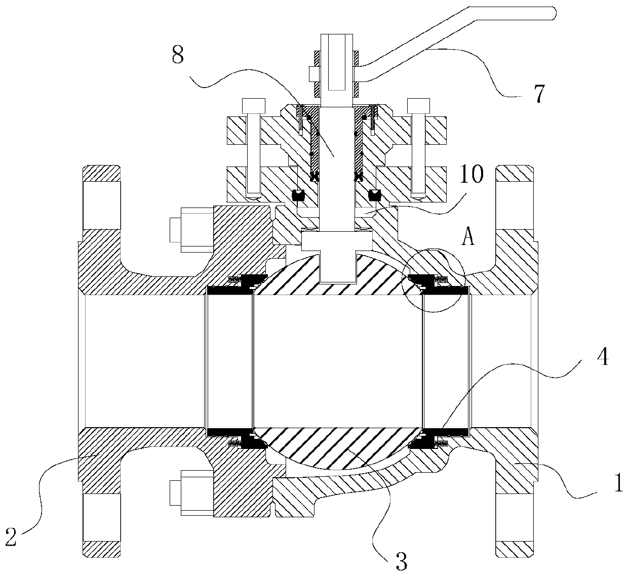
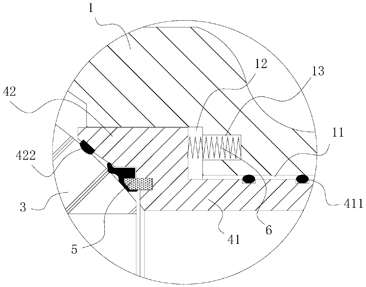
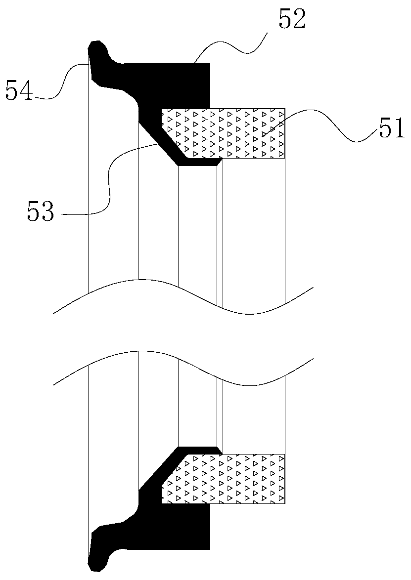
[0018] refer to Figure 1 to Figure 7 A high sealing performance ball valve of the present invention comprises an inlet valve body 1, an outlet valve body 2, a ball valve 3, a valve seat 4, a first sealing member 5, a spring 6, a handle 7 and a valve stem control mechanism 8, the inlet valve body 1 and the outlet valve body 2 form a cavity for accommodating the ball valve 3. The inlet valve body 1 and the outlet valve body 2 are installed with two symmetrically arranged valve seats 4, and the ball valve 3 is installed on two In the valve seat 4, several springs 6 are respectively installed in the inlet valve body 1 and the outlet valve body 2, and a first sealing member 5 is installed on the end of the valve seat 4 close to the ball valve 3, and the first sealing member 5 It abuts against the ball valve 3, and the other end of the valve seat 4 abuts against the spring 6. The upper part of the inlet valve body 1 is provided with a connection cavity 10 for installing the valve s...


PUM


Abstract

The invention provides a high sealing ball valve, which comprises an inlet valve body, an outlet valve body, ball valves, valve seats, first sealing elements, a spring, a handle and a valve rod control mechanism, wherein two valve seats are installed in the inlet valve body and the outlet valve body, the ball valves are installed in the two valve seats, one ends of the valve seats close to the ball valves are provided with the first sealing elements which are in abut fitting with the ball valves, the other ends of the valve seats are in abut fitting with the spring, a connecting seat, a valverod shaft, a bushing, an X-shaped sealing element and a second sealing element are arranged on the valve rod control mechanism, the outer periphery of the connecting seat is provided with the second sealing element that is closely fit with the inner wall of a connecting cavity, the bushing is sleeved outside the valve rod shaft, the valve rod shaft and the bushing are installed in the connecting seat, the X-shaped sealing element is arranged between the bottom of the bushing and the connecting seat, the bottom of the valve rod shaft is connected with the ball valves, and the top of the valve rod shaft is provided with a handle. The ball valve has good sealing performance and can prolong the service life of a product.

Description

【Technical field】 [0001] The invention relates to the technical field of ball valves, in particular to a ball valve with high sealing performance. 【Background technique】 [0002] The main features of the ball valve are its compact structure, reliable sealing, simple structure, and convenient maintenance. The sealing surface and the spherical surface are often in a closed state, which is not easily eroded by the medium, easy to operate and maintain, and is suitable for general work such as water, solvent, acid, and natural gas. Medium, but also suitable for medium with harsh working conditions, such as oxygen, hydrogen peroxide, methane and ethylene, etc. Therefore, ball valves have been widely used in various industries. Regardless of the above-mentioned valve seat of a single style or a combined style, due to various factors, the sealing of the valve seat may not be tight, resulting in medium leakage in the pipeline. Therefore, medium leakage is also one of the common probl...

Claims


Application Information

Patent Timeline
Patent Type & Authority Applications(China)
IPC IPC(8): F16K5/06F16K5/20F16K41/02
CPCF16K5/0689F16K5/0694F16K5/201F16K41/026
Inventor 李俊张忠敏粟飞郑书剑钟家富
Owner ZHEJIANG ZHONGDE AUTOMATIC CONTROL VALVE
Learn More