Medical injector
A technology of a syringe and a sealing plug, applied in the field of medical injection tools, can solve the problems of difficult operation, large push-pull force of a push rod, soreness in the hands of medical staff, etc., so as to reduce the difficulty of operation, reduce the contact area, and reduce the difficulty of pushing and pulling Effect
- Summary
- Abstract
- Description
- Claims
- Application Information
AI Technical Summary
Problems solved by technology
Method used
Image
Examples
Embodiment 1
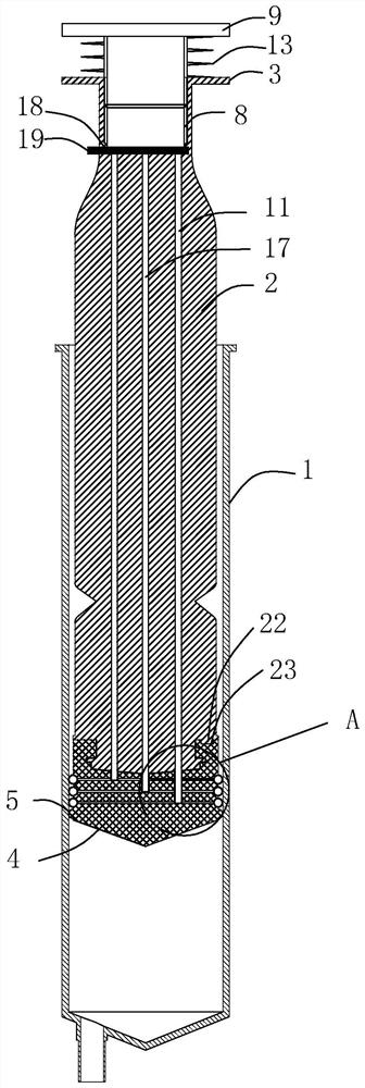
[0047] A medical syringe, see figure 1 , including a sleeve 1, a push rod 2, the two ends of the push rod 2 are respectively provided with a sealing plug 4 and a handle 3, the sealing plug 4 is located in the sleeve 1, and the material of the sealing plug 4 can be rubber. An annular sealing bead 5 is provided on the circumferential side wall of the sealing plug 4 , the material of the sealing bead 5 is consistent with that of the sealing plug 4 , and the sealing bead 5 is used to seal against the inner cylinder wall of the sleeve 1 .
[0048] Wherein, the push rod 2 includes two thin rod pieces 21, and the two thin rod pieces 21 cross each other to form a cross.
[0049] see figure 1 as well as figure 2 , the width of the thin rod sheet 21 near the handle 3 gradually becomes smaller, the center of the intersection of the two thin rod sheets 21 is concentric to the center of the handle 3, and the width of the thin rod sheet 21 is smaller than the width of the handle 3, so th...
Embodiment 2
[0051] Embodiment two: on the basis of embodiment one.
[0052] see image 3 as well as Figure 4 On the side wall of the sealing plug 4, there is an annular first air-tight covering sheet 6, and an annular first air-filling cavity 7 is formed between the first air-tight covering sheet 6 and the outer wall of the sealing plug 4. The end of the push rod 2 provided with the handle 3 is provided with an inflation hole 8 , the inflation hole 8 runs through the handle 3 , and the inflation hole 8 is internally threaded with an inflation plug 9 . The material of the inflation plug 9 itself can be selected from rubber to improve the sealing between the inner hole wall of the inflation hole 8 and the side wall of the inflation plug 9 .
[0053] see image 3 as well as Figure 4 , A first inflation channel 10 is provided in the sealing plug 4, and the first inflation channel 10 communicates with the first inflation cavity 7.
[0054] The push rod 2 is provided with a first inflata...
Embodiment 3
[0061] Embodiment three: a kind of use steps of the medical syringe shown in embodiment two:
[0062] Step 1: Medical personnel judge the injection pressure of the syringe required in the actual medical environment;
[0063] Step 2: According to the injection pressure required by the medical care environment judged in Step 1, the medical personnel do not push the sealing rubber sheet 19 and do not rotate the inflation plug 9;
[0064] Step 3: According to the injection pressure required by the medical care environment judged in step 1, the medical personnel push the sealing rubber sheet 19, and the sealing rubber sheet 19 completely covers the second inflatable aisle 17 without blocking the first inflatable aisle 11 , the medical personnel rotate the inflation plug 9, the inflation plug 9 squeezes the gas in the inflation hole 8 into the first inflation passage 11, the gas passes through the first ventilation hole 24 of the first insertion rod 12, and then enters through the f...
PUM
 Abstract
Description
Claims
Application Information
 - R&D
- Intellectual Property
- Life Sciences
- Materials
- Tech Scout
- Unparalleled Data Quality
- Higher Quality Content
- 60% Fewer Hallucinations
Browse by: Latest US Patents, China's latest patents, Technical Efficacy Thesaurus, Application Domain, Technology Topic, Popular Technical Reports.
© 2025 PatSnap. All rights reserved.Legal|Privacy policy|Modern Slavery Act Transparency Statement|Sitemap|About US| Contact US: help@patsnap.com


