
A rainwater diversion device for metal roof and metal roof

A shunt device and metal roofing technology, applied in the direction of roofing, roof drainage, roof covering, etc., can solve the problems of hidden water leakage, corrosion of lining board, hidden water leakage and other problems, achieve beautiful outer surface, avoid easy rust, and improve service life The effect of longevity

Active Publication Date: 2021-09-21
无迪(北京)装配技术有限公司
View PDF9 Cites 0 Cited by
  • Summary
  • Abstract
  • Description
  • Claims
  • Application Information

AI Technical Summary

Problems solved by technology

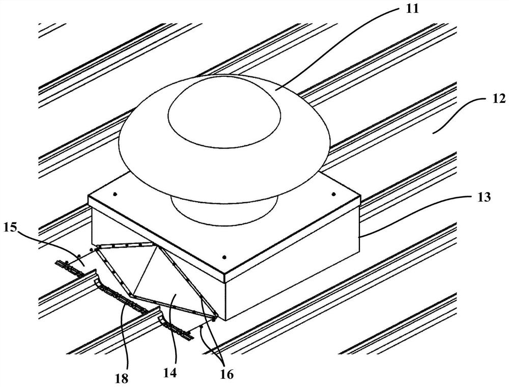
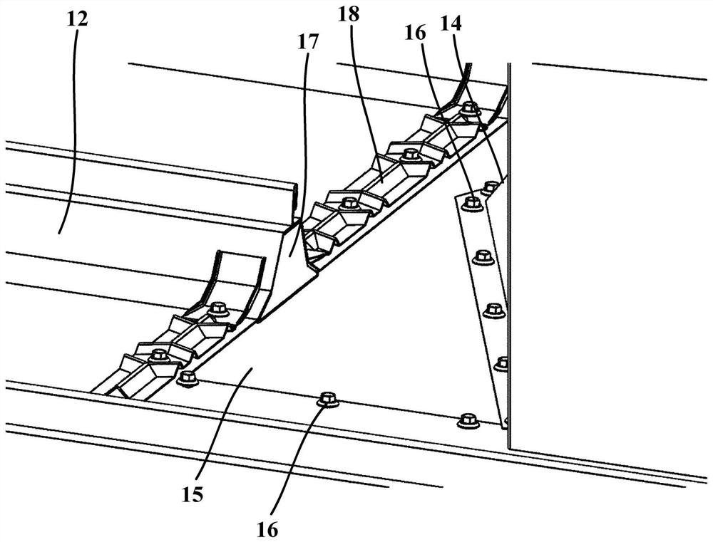
Depend on figure 1 and figure 2 As shown in the structural diagram, it can be seen that the connection between the existing profiled roof panel 12 and the base 13 has the following problems: the connection between the drain piece 14 at the front end of the base 13 and the base 13 has a large number of connecting nails 16 exposed, There is a hidden danger of water leakage; the connection between the drainage member 14 and the lining board 15 is connected by connecting nails 16, and a large number of connecting nails 16 are exposed, which has hidden dangers of water leakage; the connection between the profiled roof panel 12 and the lining board 15 is also exposed A large number of connecting nails 16 leave hidden dangers of water leakage; the profiled roof panel 12 cut on site at the front end of the base 13, the incision corrosion seriously affects the life of the roof panel 12, and will also cause corrosion of the liner 15 and the drainage piece 14; the cut pressure Type roof panel 12 crests, leaving a hole, generally there is a sealing plug 17, the reliability of its waterproof plugging has been plagued by this industry, and many other technical problems

Method used


Image

  • A rainwater diversion device for metal roof and metal roof
  • A rainwater diversion device for metal roof and metal roof
  • A rainwater diversion device for metal roof and metal roof

Examples


Embodiment Construction

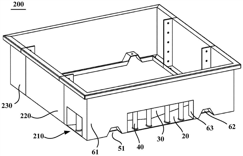
[0037] image 3 It is a schematic structural diagram of the rainwater diversion device provided by the present invention. Such as image 3 shown, and refer to Figure 4 to Figure 8 , the embodiment of the present invention provides a rainwater diversion device 200 for a metal roof, and the rainwater diversion device 200 may have a front-end drainage part 210 . The front-end drainage part 210 includes a distribution bottom plate 20 , a drainage plate 30 , a plurality of hollow columns 40 and a plurality of first connection structures.

[0038] The distribution bottom plate 20 is disposed on the upper side of the roof panel 100 of the metal roof. The diversion plate 30 extends upwards from the distribution bottom plate 20 , so that the water flowing from the front side of the distribution bottom plate 20 flows to one side or both sides of the distribution bottom plate 20 . The diversion plate 30 can be integrally formed with the distribution bottom plate 20 , for example, th...


PUM


Abstract

The invention relates to the drainage and connection technology of metal roofs, and provides a rainwater diversion device for metal roofs and the metal roof. It has a front-end drainage part, and the front-end drainage part includes: a diversion bottom plate, which is arranged on the upper side of the roof plate of the metal roof; one side or two sides of one or both sides; a plurality of hollow columns extending upward from the diversion bottom plate and located on the front side of the diversion plate; and a plurality of first connection structures, each first connection structure is installed on a corresponding hollow column, To install the splitter base plate on the roof panel. By changing the shape of the front-end drainage part and its connection with the profiled metal roof panel, the phenomenon of a large number of exposed connecting nails in the prior art profiled roof base can be completely solved, so that there are no exposed connecting nails around the base, completely. Eliminate the hidden danger of water leakage in nail holes and eliminate the corrosion of connecting nails, and make the outer surface of the metal roof beautiful.

Description

technical field [0001] The invention relates to drainage connection technology in the field of metal roofs, in particular to a rainwater diversion device for metal roofs and the metal roof. Background technique [0002] When there are more and more profiled metal roofs, people pay more and more attention to the waterproof performance of metal profiled roofs. The use of profiled metal roofs in civil buildings and public buildings is also becoming more and more widespread. At present, the waterproof performance requirements of metal roofs are getting higher and higher, especially when it is necessary to place roof pipes or axial flow fans 11 on the roof, the waterproof performance of the connection between the fan 11 and the profiled roof panel 12 is even more important. At present, the more popular practices in the industry are as follows: figure 1 and figure 2 As shown, it includes: a profiled roof panel 12, used for roof waterproofing and protection; a drainage piece 14...

Claims


Application Information

Patent Timeline
Patent Type & Authority Patents(China)
IPC IPC(8): E04D13/00E04D13/04
CPCE04D13/00E04D13/04E04D13/0409E04D2013/0422
Inventor 赵静青
Owner 无迪(北京)装配技术有限公司
Learn More