Profile stretch bending device for aircraft manufacturing

A technology for aircraft manufacturing and profiles, which is applied in the field of profile drawing and bending devices for aircraft manufacturing, can solve problems such as damage to the device mechanism, damage to the profile by the clamping mechanism, instability, etc., so as to improve the life of the device, improve the detection effect, and avoid damage. The effect of profiles

Active Publication Date: 2020-06-19
公主岭市大鹏航空设备有限公司
View PDF9 Cites 1 Cited by
  • Summary
  • Abstract
  • Description
  • Claims
  • Application Information

AI Technical Summary

Problems solved by technology

The clamping part in the above-mentioned patent has the following disadvantages: the clamping mechanism is relatively fixed, and due to its instability during the process of bending and shaping the profile, the clamping mechanism may damage the profile or cause damage to the device mechanism

Method used


Image

  • Profile stretch bending device for aircraft manufacturing
  • Profile stretch bending device for aircraft manufacturing
  • Profile stretch bending device for aircraft manufacturing

Examples


Embodiment 1

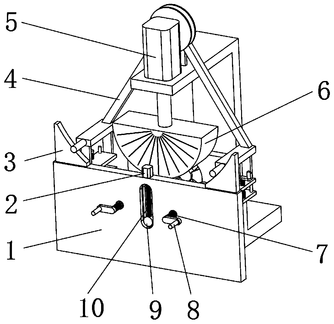
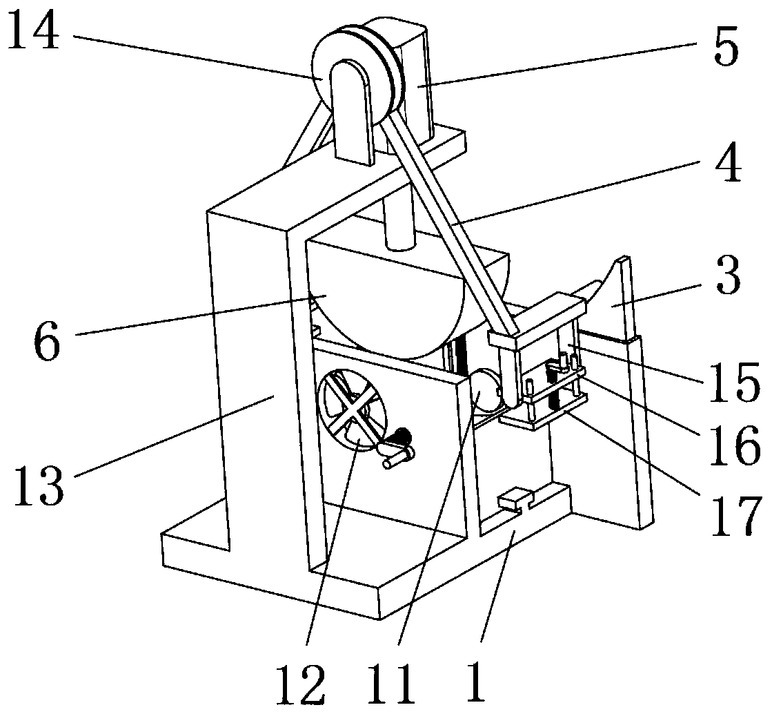
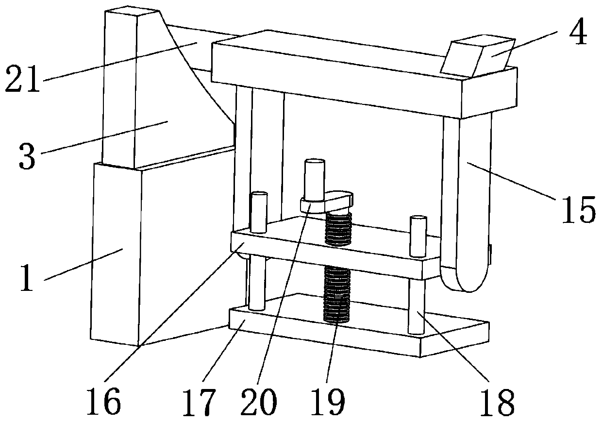
[0036] A profile stretch bending device for aircraft manufacturing, such as Figure 1-3 As shown, it includes a base 1, a pressing mechanism, a clamping mechanism and a detection mechanism; the outer wall of one side of the base 1 is welded with a mounting frame 13, and the pressing mechanism includes a hydraulic cylinder 5 and a bending head 6, and the hydraulic cylinder 5 is fixed to the top outer wall of the installation frame 13 by bolts, and the output end of the installation frame 13 is fixed to the top outer wall of the bending head 6 by bolts; the clamping mechanism includes two connecting arms 4, two connecting frames 15, two A first splint 16 and two second splints 17; the top outer wall of the mounting frame 13 is fixed with a turntable assembly 14 by bolts, and the connecting arm 4 has a symmetrical structure; and the inner wall at one end of the connecting arm 4 is slidably connected to the turntable through a support shaft The inner walls on both sides of the com...

Embodiment 2

[0047] A profile stretch bending device for aircraft manufacturing, such as Figure 6 As shown, in order to improve the processing effect; this embodiment makes the following improvements on the basis of Embodiment 1: the outer wall of one side of the turntable assembly 14 is fixed with a second motor 27 through the second motor base, and the outer wall of the other side of the turntable assembly 14 The third motor base is fixed with a third motor 28, the output end of the second motor 27 is connected to the outer wall of one connecting arm 4 through a synchronous wheel, and the output end of the third motor 28 is connected to the outer wall of another connecting arm 4 through a synchronous wheel. ; By arranging the second motor 27 and the third motor 28, it is possible to cooperate with stretching during the pressing process and improve the processing effect.

[0048] When this embodiment is in use, when the pressing mechanism presses the profiles, the second motor 27 and the...


PUM


Abstract

The invention discloses a profile stretch bending device for aircraft manufacturing, and relates to the technical field of aircraft profile machining. The profile stretch bending device particularly comprises a base, a pressing mechanism, a clamping mechanism and a detecting mechanism. A mounting rack is welded to the outer wall of one side of the base, and the pressing mechanism comprises a hydraulic cylinder and a bending head. The hydraulic cylinder is fixedly mounted on the outer wall of the top of the mounting rack through a bolt. The output end of the mounting rack is fixed to the outerwall of the top of the bending head. The clamping mechanism comprises two connecting arms, two connecting frames, two first clamping plates and two second clamping plates. According to the profile stretch bending device, the pressing mechanism is arranged, and therefore a profile can be bent; the clamping mechanism is arranged, and therefore the two ends of the profile can be clamped, and the workstability is guaranteed; the first clamping plates are mounted on the inner walls of the connecting frames through shafts and bearings, and therefore the angle can be changed in real time when the profile deforms; and the profile is prevented from being damaged, and meanwhile the service life of the device is prolonged

Description

technical field [0001] The invention relates to the technical field of aircraft profile processing, in particular to a profile stretch bending device for aircraft manufacturing. Background technique [0002] With the development of science and technology, transportation is becoming more and more developed, and people's lives have become more convenient. As a fast and efficient means of transportation, airplanes are also widely used by people. In the manufacturing process of airplanes, the processing of its profiles is inevitable. Profile stretch bending devices are used, and some profile stretch bending devices have low reliability and the use effect is not ideal. [0003] After searching, the Chinese patent application number is CN201410708666.2, which discloses a metal profile stretch bending device, which is used to stretch and bend metal profiles. surface; the clamping and bending part, including: the clamping part for clamping the metal profile, and the stretching and ...

Claims


Application Information

Patent Timeline
Patent Type & Authority Applications(China)
IPC IPC(8): B21D7/06B21D7/14B21D7/16B21D43/00B21D37/16B21C51/00
CPCB21D7/06B21D7/14B21D7/162B21D7/165B21D43/003B21D37/16B21C51/00
Inventor 李春丽赵志强崔希敏王艳
Owner 公主岭市大鹏航空设备有限公司
Why Eureka
Try Eureka