Shoe with optical fiber vamp and manufacturing method thereof
A technology for uppers and optical fibers, applied in soles, uppers, footwear, etc., can solve the problems of lack of interest and recognition, inability to illuminate areas independently, and inability to apply to the use environment of smart shoes, so as to increase aesthetics and interest Non-toxic, not easy to disperse, low power consumption
- Summary
- Abstract
- Description
- Claims
- Application Information
AI Technical Summary
Problems solved by technology
Method used
Image


Examples
Embodiment 1
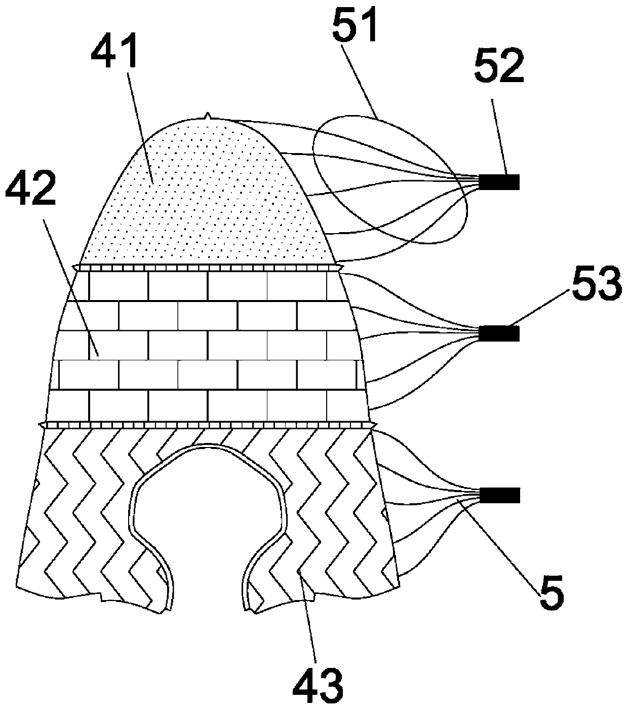
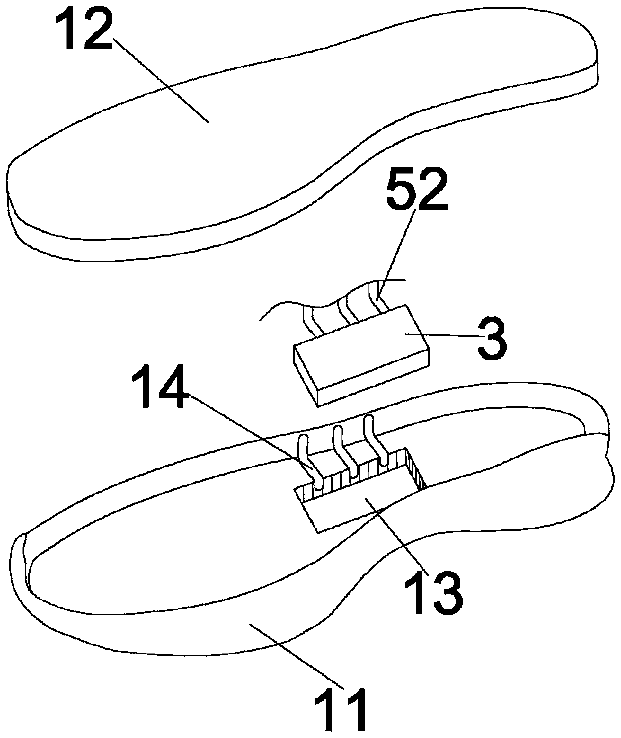
[0045] Such as Figure 1-2As shown, a shoe with an optical fiber upper includes a sole 1 and an upper 2, the upper 2 is glued to the sole 1, the sole 1 is integrated with a control device 3, and the control device 3 includes a microprocessor device 31, illuminant 32, power supply 33, and control switch 34. The vamp 2 includes three vamp regions 4, which are A region 41, B region 42, and C region 43. The area A 41 is the upper area 4 corresponding to the toe cap, that is, the area where part of the optical fiber 51 and the upper 2 are integrated through electric embroidery or weaving is the toe area. The B zone 42 is the upper region 4 corresponding to the arch of the foot, that is, the area where the part of the optical fiber 51 and the upper 2 are integrated through electric embroidery or weaving is the arch region of the foot. The C area 43 is the upper area 4 corresponding to the heel, that is, the routing range of part of the optical fiber 51 and the upper 2 through elect...
Embodiment 2
[0060] Such as Figure 1-2 As shown, a shoe with an optical fiber upper includes a sole 1 and an upper 2, the upper 2 is glued to the sole 1, the sole 1 is integrated with a control device 3, and the control device 3 includes a microprocessor device 31, illuminant 32, power supply 33, and control switch 34. The vamp 2 includes three vamp regions 4, which are A region 41, B region 42, and C region 43. The area A 41 is the upper area 4 corresponding to the toe cap, that is, the area where part of the optical fiber 51 and the upper 2 are integrated through electric embroidery or weaving is the toe area. The B area 42 is the upper area 4 corresponding to the arch of the foot, that is, the range of routing when part of the optical fiber 51 and the upper are integrated through electric embroidery or weaving is the arch area of the foot. The C area 43 is the upper area 4 corresponding to the heel, that is, the routing range of part of the optical fiber 51 and the upper 2 through e...
Embodiment 3
[0075] Such as Figure 1-2 As shown, a shoe with an optical fiber upper includes a sole 1 and an upper 2, the upper 2 is glued to the sole 1, the sole 1 is integrated with a control device 3, and the control device 3 includes a microprocessor device 31, illuminant 32, power supply 33, and control switch 34. The vamp 2 includes three vamp regions 4, which are A region 41, B region 42, and C region 43. The area A 41 is the upper area 4 corresponding to the toe cap, that is, the area where part of the optical fiber 51 and the upper 2 are integrated through electric embroidery or weaving is the toe area. The B zone 42 is the upper region 4 corresponding to the arch of the foot, that is, the area where the part of the optical fiber 51 and the upper 2 are integrated through electric embroidery or weaving is the arch region of the foot. The C area 43 is the upper area 4 corresponding to the heel, that is, the routing range of part of the optical fiber 51 and the upper 2 through elec...
PUM
 Abstract
Description
Claims
Application Information
 - R&D
- Intellectual Property
- Life Sciences
- Materials
- Tech Scout
- Unparalleled Data Quality
- Higher Quality Content
- 60% Fewer Hallucinations
Browse by: Latest US Patents, China's latest patents, Technical Efficacy Thesaurus, Application Domain, Technology Topic, Popular Technical Reports.
© 2025 PatSnap. All rights reserved.Legal|Privacy policy|Modern Slavery Act Transparency Statement|Sitemap|About US| Contact US: help@patsnap.com