Lidar arrangement, vehicle, and robot comprising a lidar arrangement of this type

A lidar and component technology, applied in the field of vehicles and robots, can solve problems such as limiting the detection range, and achieve the effect of safety assurance

Active Publication Date: 2020-06-16
ROBERT BOSCH GMBH
View PDF4 Cites 0 Cited by
  • Summary
  • Abstract
  • Description
  • Claims
  • Application Information

AI Technical Summary

Problems solved by technology

In any case, except in special cases, only a very small light component of the backscattered light scattered back by the object hits the detector unit, which correspondingly limits the detection range
For eye safety reasons, the laser power can only be increased up to certain limit values

Method used


Image

  • Lidar arrangement, vehicle, and robot comprising a lidar arrangement of this type
  • Lidar arrangement, vehicle, and robot comprising a lidar arrangement of this type
  • Lidar arrangement, vehicle, and robot comprising a lidar arrangement of this type

Examples


Embodiment Construction

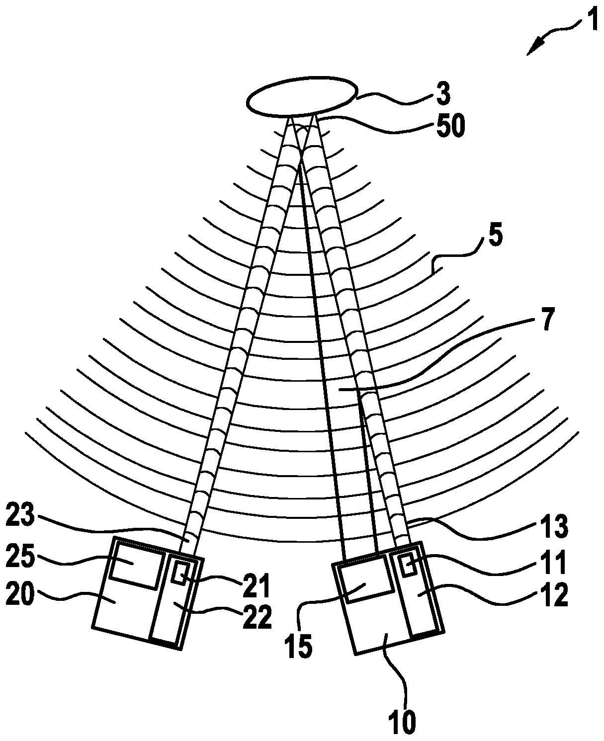
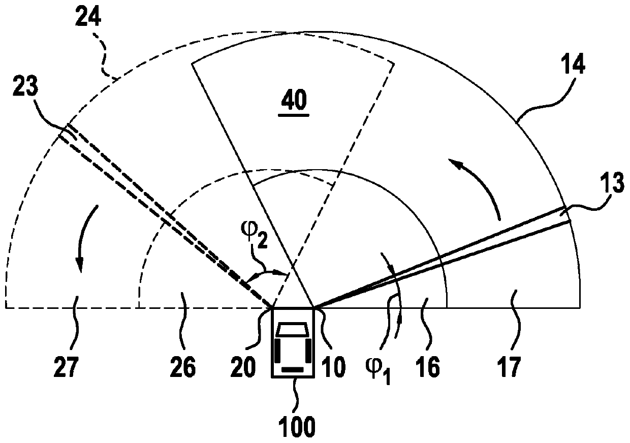
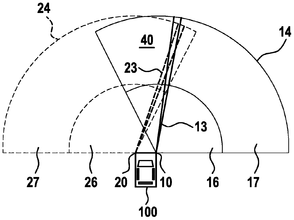
[0028] exist figure 1 A lidar assembly 1 according to the invention is shown in . In this case, the lidar assembly includes a first lidar system 10 . Furthermore, the first lidar system 10 also includes a first laser source 11 generating a first laser beam 13 . Furthermore, the first lidar system 10 also includes a first scanning device 12 which scans a first laser beam 13 over a first scanning range 14 . Here, it is especially possible to combine figure 2 and image 3 An example of the first scanning area 14 is understood.

[0029] Furthermore, the lidar assembly 1 includes a second lidar system 20 . In this case, the second laser radar system 20 also includes a second laser light source 21 which generates a second laser beam 23 . Furthermore, the second lidar system 20 also includes a second scanning device 22 which scans a second laser beam 23 over a second scanning range 24 .

[0030] Here, in an exemplary embodiment, the second scanning area 24 can also be from fi...


PUM


Abstract

The invention relates to a LIDAR assembly (1) comprising a plurality of LIDAR systems (10, 20). The first LIDAR system (10) is spaced apart from the second LIDAR system (20). A first laser beam (13) of the first LIDAR system (10) and a second laser beam (23) are synchronized such that said first laser beam (13) and second laser beam (23) are mutually amplifying in a common remote region (50).

Description

technical field [0001] The invention relates to a laser radar assembly, a vehicle and a robot with the laser radar assembly. Background technique [0002] The scanning laser radar system (lidar = light detection and ranging) scans a certain scanning area or spatial area with a pulsed laser beam, and calculates the existence and distance of the object hit by the laser beam. In this case, a lidar system usually has a laser source for generating a laser beam, a scanning device for scanning the emitted laser beam over a certain scanning area, and a detector unit for detecting the backscattered light. There are various alternatives for the scanning device here. For example, the detector unit and the laser may be pivoted together by the scanning device, only the laser pivoted, or beam deflecting elements such as micromirrors or polygons scan the laser beam. [0003] If the laser beam hits the object, the reflected light or the backscattered light is distributed over a wide spati...

Claims


Application Information

Patent Timeline
Patent Type & Authority Applications(China)
IPC IPC(8): G01S17/87G01S17/931G01S7/484
CPCG01S17/87G01S7/484G01S7/4817G01S17/931G01S17/48
Inventor I·拉姆斯泰纳
Owner ROBERT BOSCH GMBH
Why Eureka
Try Eureka