


Quick Research
Generate reliable direction feasibility study reports for your R&D in just a few steps.

Technical Q&A
Discover and master advanced knowledge NOW. Basics, ideas, possibilities, all at once.

Find Solutions
As an expert in R&D theories, this can generate solutions to your technical problems instantly.

Evaluate Feasibility
Analyze your overall solution with one click, know your potential R&D risks in advance.

Monitor Landscape
Get weekly tech updates, stay abreast of the latest tech innovations and key insights.
An ultra-low nitrogen burner for oilfield heating furnace
A heating furnace, ultra-low nitrogen technology, applied in the direction of burner, gas fuel burner, combustion type, etc., can solve the problems of complex gas source, no molding available products, harsh environment, etc., to achieve long maintenance period and convenient maintenance The effect of high cost and work efficiency
- Summary
- Abstract
- Description
- Claims
- Application Information
AI Technical Summary
Problems solved by technology
Method used
Image

Examples
Embodiment 1
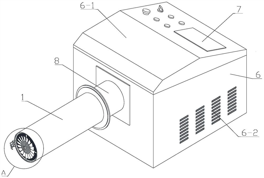
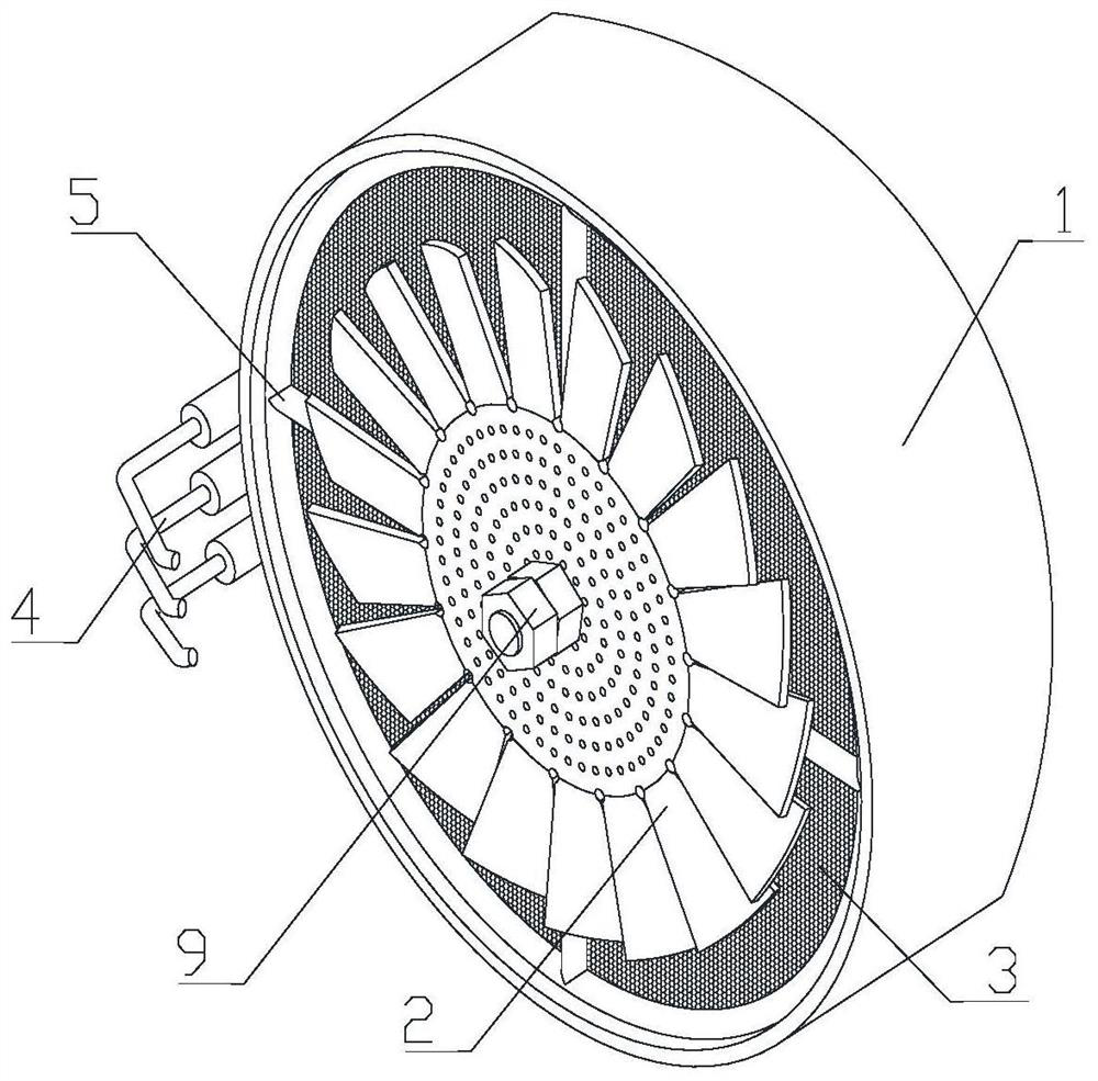
[0032] see Figure 1 to Figure 5 , the embodiment of the present invention provides an ultra-low nitrogen burner for an oil field heating furnace, which includes a fan, and an outer cylinder 1 communicated with the air outlet of the fan, placed in the outer cylinder 1, and connected to the inner wall of the outer cylinder 1 The matching porous filler 3 is installed at the outer port of the outer cylinder 1, and the rotating vane orifice plate 2 whose normal direction is parallel to the direction of the centerline of the outer cylinder 1 is arranged at the outer port of the outer cylinder 1 and is located outside the rotating vane orifice plate 2 The firing pin 4 and the display control unit 7 electrically connected to the fan and the firing pin 4 respectively. When in use, a certain proportion of combustible gas and air premixed gas is blown into the outer cylinder by the air inlet of the fan through the fan. 1. After the premixed gas passes through the porous filler 3 and the...
Embodiment 2
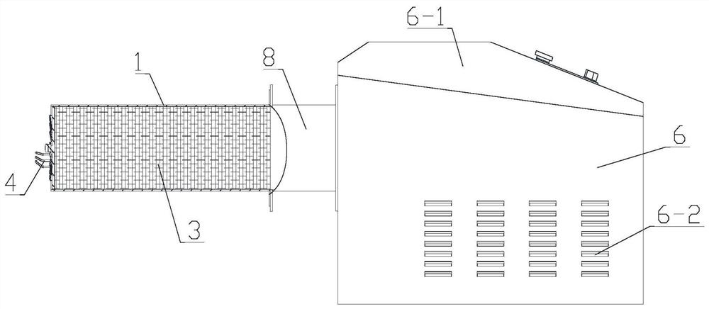
[0042] see image 3, on the basis of Example 1, the others are the same as Example 1, the difference from Example 1 is that the porous filler 3 extends from the inner port of the outer cylinder 1 to the inner side of the rotary vane orifice plate 2, close to the rotary vane orifice plate 2 In this position, the filling length of the porous filler 3 is ensured, thereby ensuring the travel of the premixed gas in the porous filler 3, so that the premixed gas can be mixed uniformly.
Embodiment 3
[0044] see figure 2 and image 3 , on the basis of Example 2, the others are the same as Example 2, and the difference from Example 2 is that the porous filler 3 is provided with several layers of stainless steel honeycomb panels evenly stacked along the centerline direction of the outer cylinder 1, and each layer The diameter of the stainless steel honeycomb plate matches the inner diameter of the outer cylinder 1, which is convenient for materials and easy to make.
[0045] The holes of the adjacent two layers of stainless steel honeycomb panels are staggered and communicated, so that the premixed gas advances along the zigzag channel when passing through the porous filler 3, which increases the stroke of the premixed gas and further ensures the uniform mixing of the premixed gas.
PUM
 Abstract
Description
Claims
Application Information
 - R&D Engineer
- R&D Manager
- IP Professional
- Industry Leading Data Capabilities
- Powerful AI technology
- Patent DNA Extraction
Browse by: Latest US Patents, China's latest patents, Technical Efficacy Thesaurus, Application Domain, Technology Topic, Popular Technical Reports.
© 2024 PatSnap. All rights reserved.Legal|Privacy policy|Modern Slavery Act Transparency Statement|Sitemap|About US| Contact US: help@patsnap.com