
Calibration system and calibration bracket thereof

A technology for calibrating and calibrating components, applied in machine/support, radio wave measurement system, supporting machine, etc., can solve problems such as beam instability

Pending Publication Date: 2020-06-16
AUTEL INTELLIGENT TECHNOLOGY CORP LTD
View PDF0 Cites 3 Cited by
  • Summary
  • Abstract
  • Description
  • Claims
  • Application Information

AI Technical Summary

Problems solved by technology

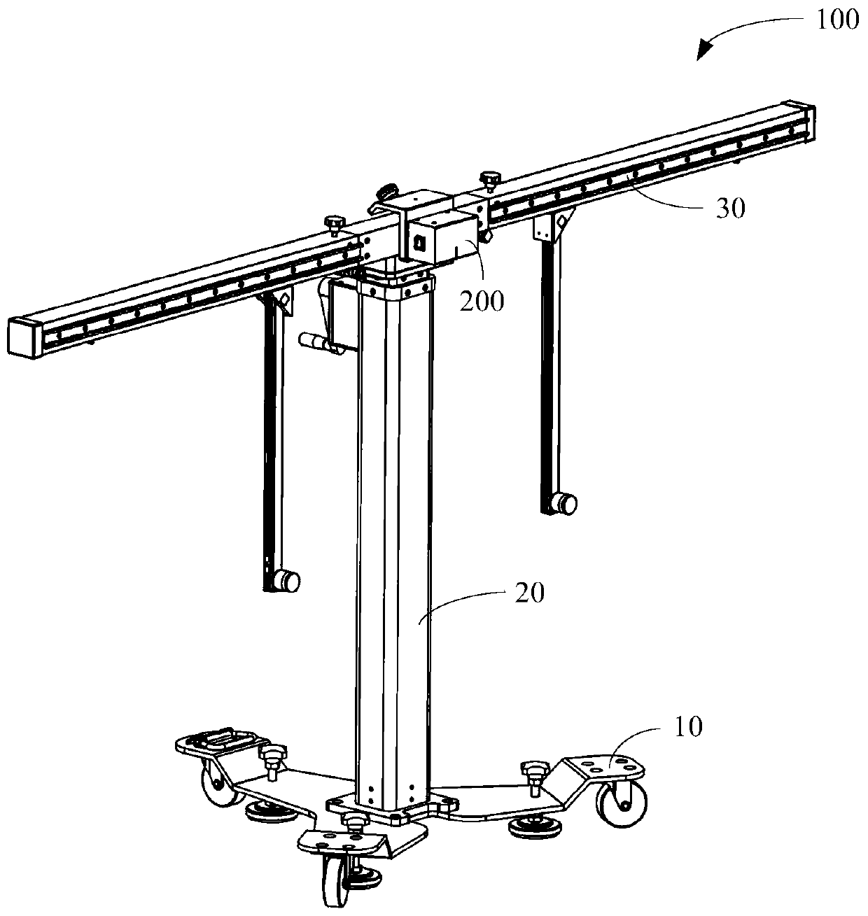
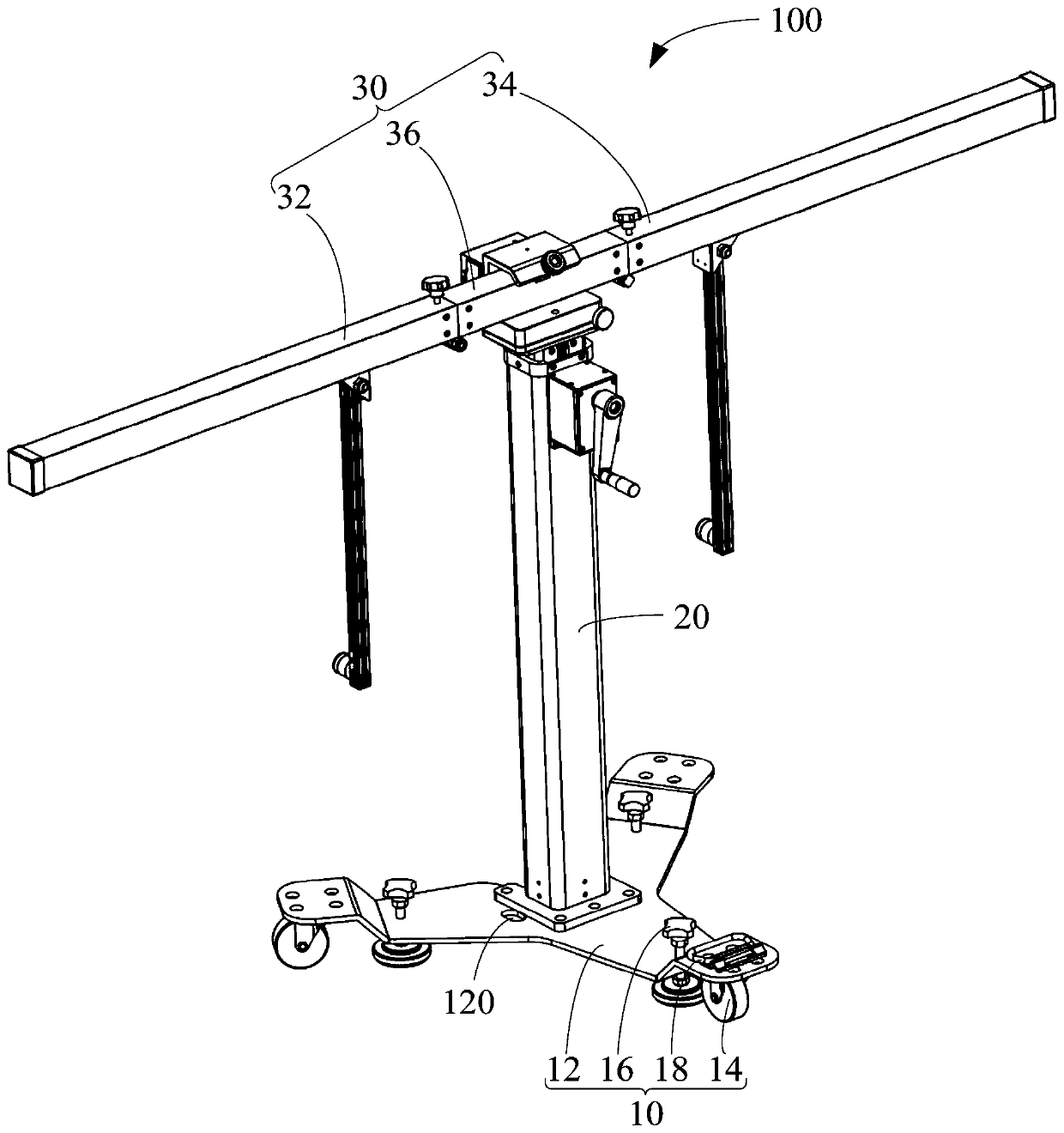
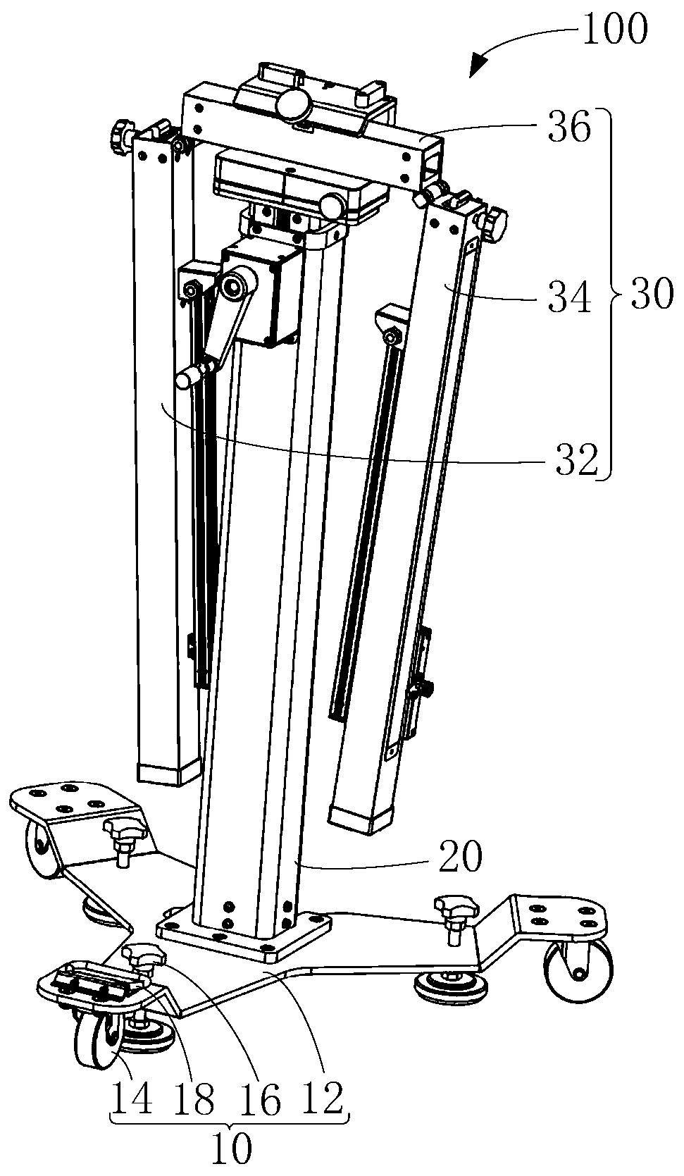
[0004] The embodiment of the present application aims to provide a calibration system and its calibration bracket, which can solve the problem in the prior art that the beam of the calibration bracket is unstable after mounting the calibration components

Method used


Image

  • Calibration system and calibration bracket thereof
  • Calibration system and calibration bracket thereof
  • Calibration system and calibration bracket thereof

Examples


Embodiment Construction

[0036] In order to facilitate the understanding of the present application, the present application will be described in more detail below in conjunction with the accompanying drawings and specific embodiments. It should be noted that when an element is said to be "fixed" to another element, it may be directly on the other element, or there may be one or more intervening elements therebetween. When an element is referred to as being "connected to" another element, it can be directly connected to the other element or one or more intervening elements may be present therebetween. The orientation or positional relationship indicated by the terms "upper", "lower", "inner", "outer", "vertical", "horizontal" etc. used in this specification is based on the orientation or positional relationship shown in the drawings, It is only for the purpose of describing the present application and simplifying the description, but does not indicate or imply that the device or element referred to mu...


PUM


Abstract

The application relates to the field of vehicle calibration, and provides a calibration system and a calibration bracket thereof. The calibration bracket comprises a base, a fixed vertical rod, a mobile vertical rod, a brake piece and a mounting piece, wherein one end of the fixed vertical rod is mounted on the base; the mobile vertical rod can move relative to the fixed vertical rod in the lengthdirection of the fixed vertical rod; the brake piece is used for providing friction force for driving the mobile vertical rod to fix relative to the fixed vertical rod in the length direction of thefixed vertical rod; the mounting piece is mounted on the mobile vertical rod, and is used for mounting a calibration element; and the calibration element is used for calibrating an advanced driver assistant system of a vehicle. By configuring the brake piece, the brake piece provides the friction force for driving the mobile vertical rod to fix relative to the fixed vertical rod in the length direction of the fixed vertical rod, so that a cross beam can be stable after the calibrating element is mounted.

Description

technical field [0001] The application relates to the technical field of vehicle maintenance and equipment calibration, in particular to a calibration system and a calibration bracket thereof. Background technique [0002] Advanced Driver Assistant System (ADAS), referred to as ADAS, is to use various sensors installed on the car to collect environmental data inside and outside the car at the first time, and to identify, detect and control static and dynamic objects. Tracking and other technical processing, so that the driver can detect possible dangers in the fastest time, so as to attract attention and improve safety. Active safety technology. The sensors used in ADAS mainly include cameras, radars, lasers and ultrasonics, etc., which can detect light, heat, pressure or other variables used to monitor the state of the car. They are usually located in the front and rear bumpers, side mirrors, inside the steering column or windshield of the vehicle. on the glass. During th...

Claims


Application Information

Patent Timeline
IPC IPC(8): F16M11/04F16M11/18F16M11/24F16M11/28F16M11/42G01D18/00G01S7/40
CPCF16M11/04F16M11/18F16M11/24F16M11/28F16M11/42G01D18/00G01S7/40F16M2200/027F16M2200/066G01M13/00G01M17/00G01S7/4086F16M11/38F16M11/041F16M11/2014
Inventor 刘连军张凯凯
Owner AUTEL INTELLIGENT TECHNOLOGY CORP LTD
Learn More