
Motor winding temperature estimation and protection method

A technology of motor winding and winding temperature, applied in the direction of motor control, electrical components, model/simulation of control purposes, etc., can solve the problems of motor malfunction control accuracy, complex heat dissipation device, difficult servo system, etc., to achieve the effect of improving accuracy

Active Publication Date: 2020-06-12
HANGZHOU DIANZI UNIV
View PDF9 Cites 4 Cited by
  • Summary
  • Abstract
  • Description
  • Claims
  • Application Information

AI Technical Summary

Problems solved by technology

[0005] In the prior art, the estimation of the motor winding temperature is mainly divided into the following two methods. The first method uses the relationship between the motor winding resistance and the winding temperature to calculate the winding temperature based on the winding resistance. This method needs to detect the relationship between voltage and current Calculating the resistance value of the winding requires voltage injection, which may cause malfunction of the motor and decrease the control accuracy, so it is difficult to apply to the servo system with high precision requirements. The second type uses the calculation of the equivalent thermal resistance from the winding to the outer surface of the heat dissipation shell and Copper loss and other stator losses are used to calculate the winding temperature, using either a thermodynamic model or a thermal circuit method. This method requires more accurate prior information of the winding heat dissipation model. However, this method is complex and uncertain when the heat dissipation device is relatively large in the actual application process. It is relatively difficult, so this method is difficult to apply to the winding temperature calculation under the complex heat dissipation structure under which the thermodynamic model is difficult to obtain accurately

Method used


Image

  • Motor winding temperature estimation and protection method
  • Motor winding temperature estimation and protection method
  • Motor winding temperature estimation and protection method

Examples


Embodiment Construction

[0042] In order to make the object, technical solution and advantages of the present invention clearer, the present invention will be further described in detail below in conjunction with the accompanying drawings and embodiments. It should be understood that the specific embodiments described here are only used to explain the present invention, not to limit the present invention.

[0043] On the contrary, the invention covers any alternatives, modifications, equivalent methods and schemes within the spirit and scope of the invention as defined by the claims. Further, in order to make the public have a better understanding of the present invention, some specific details are described in detail in the detailed description of the present invention below. The present invention can be fully understood by those skilled in the art without the description of these detailed parts.

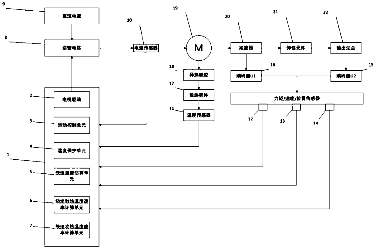
[0044] The applicable hardware structure of the method of the present invention is with figure 1 Show...


PUM


Abstract

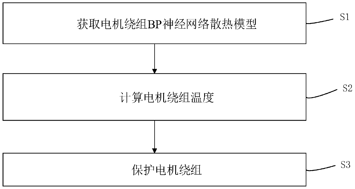
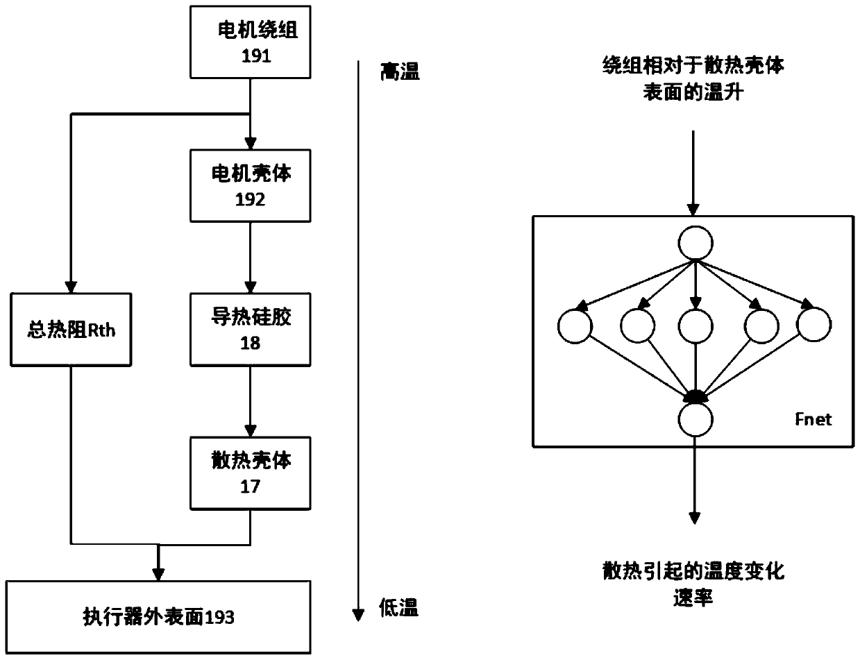
The invention discloses a motor winding temperature estimation and protection method. The method comprises the following steps: S1, obtaining a BP neural network heat dissipation model of a motor winding; S2, calculating the temperature of a motor winding; S3, protecting a motor winding. Due to the fact that the neural network can conduct accurate modeling on the heat dissipation process under thecomplex heat dissipation condition, the method is more suitable for application scenes with the complex heat dissipation condition; a winding heating temperature change rate caused by loss is calculated by using the motor winding current; the winding temperature is calculated according to the winding heat dissipation temperature change rate and the winding heating temperature change rate; the calculated winding temperature is used to limit motion control output of the motor by using a multi-segment temperature cut-off curve so as to carry out temperature protection on the winding and preventdamage caused by overhigh temperature of the winding.

Description

technical field [0001] The invention belongs to the field of motors, and relates to a method for estimating and protecting the temperature of motor windings. Background technique [0002] In the field of robotics, motors are playing an increasingly important role as electromechanical energy conversion devices. With the advancement of robot technology, the volume and quality of robots are becoming smaller and smaller, which requires high-power-density motors as drive mechanisms. Traditional It is difficult for the current protection technology to make the motor run beyond the maximum sustainable current, so that it cannot provide high peak torque to improve the transient response capability of the robot joints. However, when the motor is running, a temperature sensor is placed on the winding to detect the winding temperature in real time and monitor Protection usually leads to an increase in the size of the motor, so when the motor is running, the temperature sensor is often ...

Claims


Application Information

Patent Timeline
Patent Type & Authority Applications(China)
IPC IPC(8): H02P29/64H02P6/34
CPCH02P6/34H02P29/64
Inventor 张安龙王伟凡林志赟韩志敏
Owner HANGZHOU DIANZI UNIV
Learn More