
Crack detection method and device and additive manufacturing system

A crack detection and additive manufacturing technology, applied in the field of additive manufacturing, can solve problems such as insufficient monitoring depth, difficult crack monitoring, and undetectable cracks

Active Publication Date: 2020-06-12
SOUTH UNIVERSITY OF SCIENCE AND TECHNOLOGY OF CHINA
View PDF4 Cites 2 Cited by
  • Summary
  • Abstract
  • Description
  • Claims
  • Application Information

AI Technical Summary

Problems solved by technology

Traditional crack detection methods such as magnetic particle testing, penetrant testing, eddy current testing, ray testing, ultrasonic testing, CCD (charge coupled device, charge coupled device image sensor) imaging testing, etc. are difficult to monitor cracks in real time and efficiently
For many large components, such as nuclear power components with a diameter of more than 5 meters, the existing crack detection methods still have insufficient monitoring depth, and internal cracks and other defects cannot be detected

Method used


Image

  • Crack detection method and device and additive manufacturing system
  • Crack detection method and device and additive manufacturing system
  • Crack detection method and device and additive manufacturing system

Examples


Embodiment Construction

[0045] The present invention will be further described in detail below in conjunction with the accompanying drawings and embodiments. It should be understood that the specific embodiments described here are only used to explain the present invention, but not to limit the present invention. In addition, it should be noted that, for the convenience of description, only some structures related to the present invention are shown in the drawings but not all structures.

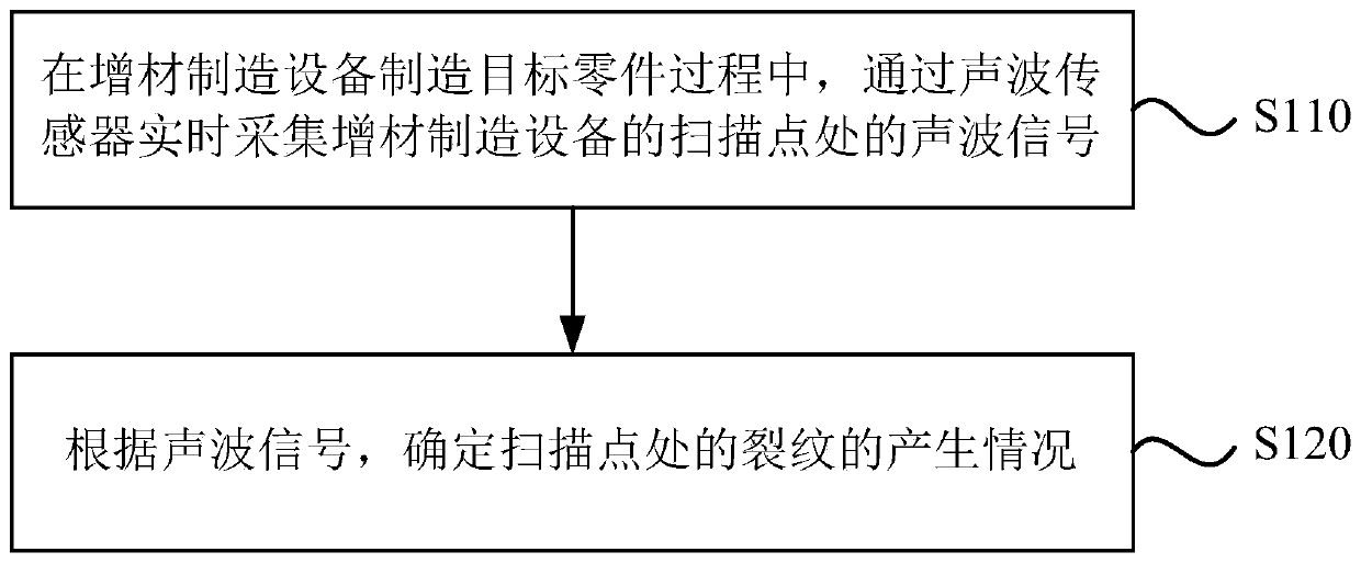
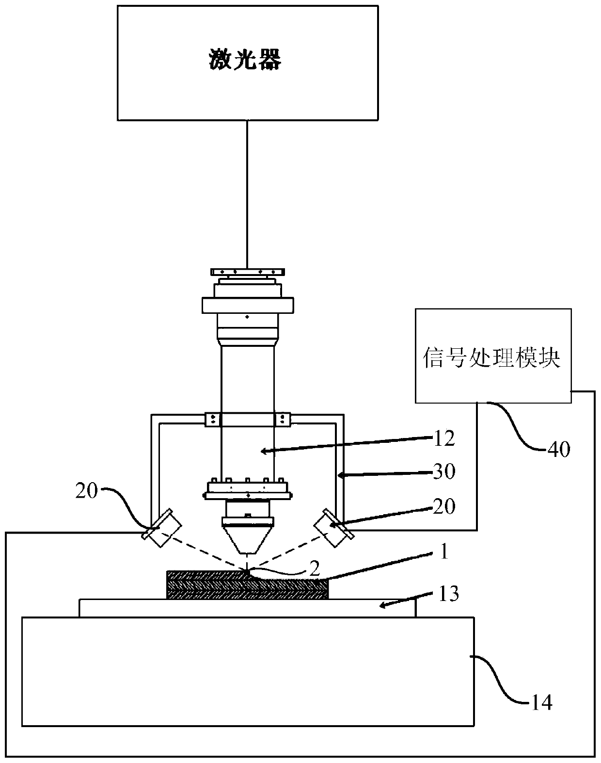
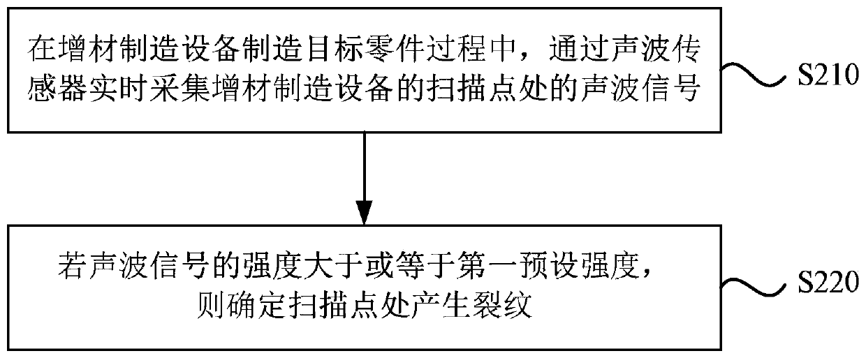
[0046] An embodiment of the present invention provides a crack detection method. figure 1 It is a flowchart of a crack detection method provided by an embodiment of the present invention. figure 2 It is a structural schematic diagram of an additive manufacturing system when an additive manufacturing equipment manufactures a target part provided by an embodiment of the present invention. The crack detection method can be executed by a crack detection device, and the device can be realized by software and / or hardw...


PUM


Abstract

The embodiment of the invention discloses a crack detection method and device and an additive manufacturing system. The crack detection method comprises the following steps of in the process of manufacturing a target part by an additive manufacturing device, acquiring a sound wave signal at a scanning point of the additive manufacturing device in real time through a sound wave sensor; and according to the sound wave signal, determining the generation condition of the crack at the scanning point. According to the technical scheme of the embodiment of the invention, the real-time nondestructivemonitoring can be carried out on the parts in the additive manufacturing process, and the crack generation moment and position of the part can be accurately obtained.

Description

technical field [0001] The invention relates to the technical field of additive manufacturing, in particular to a crack detection method and device and an additive manufacturing system. Background technique [0002] Additive Manufacturing (AM), commonly known as 3D printing, combines computer-aided design, material processing and forming technology, based on digital model files, and uses software and numerical control system to integrate special metal materials, non-metal materials and medical biomaterials , According to extrusion, sintering, melting, photo-curing, spraying and other ways to accumulate layer by layer, the manufacturing technology of manufacturing physical objects. [0003] In recent years, the demand for high-performance metal parts has been increasing in the fields of aerospace, national defense, nuclear power, marine and high-end mechanical equipment. Taking the aero engine as an example, its core components are mainly made of high-performance nickel-base...

Claims


Application Information

Patent Timeline
Patent Type & Authority Applications(China)
IPC IPC(8): G01N29/04G01N29/14G01N29/12G01N29/11B33Y40/00
CPCG01N29/04G01N29/14G01N29/11G01N29/12B33Y40/00G01N2291/015G01N2291/0234G01N2291/0289Y02P10/25
Inventor 刘朝阳朱强李欣蔚胡小刚郁峥嵘舒家阳严明唐茂倍
Owner SOUTH UNIVERSITY OF SCIENCE AND TECHNOLOGY OF CHINA
Learn More