Steel-wood composite shock-isolation pad foundation and its installation method

A technology of steel-wood combination and vibration-isolation pad, which is applied in the direction of basic structure engineering, earthquake-proof, building type, etc., can solve the problems of affecting the safety of vibration-isolation bearings, no vibration reduction effect, complicated installation process, etc., and achieve good reset effect, Good anti-seismic effect and the effect of reducing project cost

Active Publication Date: 2021-09-03
QINGDAO TECHNOLOGICAL UNIVERSITY
View PDF9 Cites 0 Cited by
  • Summary
  • Abstract
  • Description
  • Claims
  • Application Information

AI Technical Summary

Problems solved by technology

However, there are certain problems in the above-mentioned systems. The main disadvantage of the laminated rubber bearing isolation system is that it generally has no damping effect on vertical vibration, and it is easy to resonate with horizontal vibration with a long natural vibration period, which affects the isolation. The safety of the bearing itself; and the traditional laminated rubber seismic isolation bearing has problems such as heavy weight, high cost, and complicated installation process. Although its production technology is basically mature, there is still room for improvement and improvement in material performance. In addition , the early friction-slip isolation mostly set a strip-shaped slip layer along the strip foundation, which is undoubtedly economical, but there are many problems such as difficult construction leveling and reset

Method used


Image

  • Steel-wood composite shock-isolation pad foundation and its installation method
  • Steel-wood composite shock-isolation pad foundation and its installation method
  • Steel-wood composite shock-isolation pad foundation and its installation method

Examples


Embodiment Construction

[0044] The present invention will be further described below in conjunction with accompanying drawing.

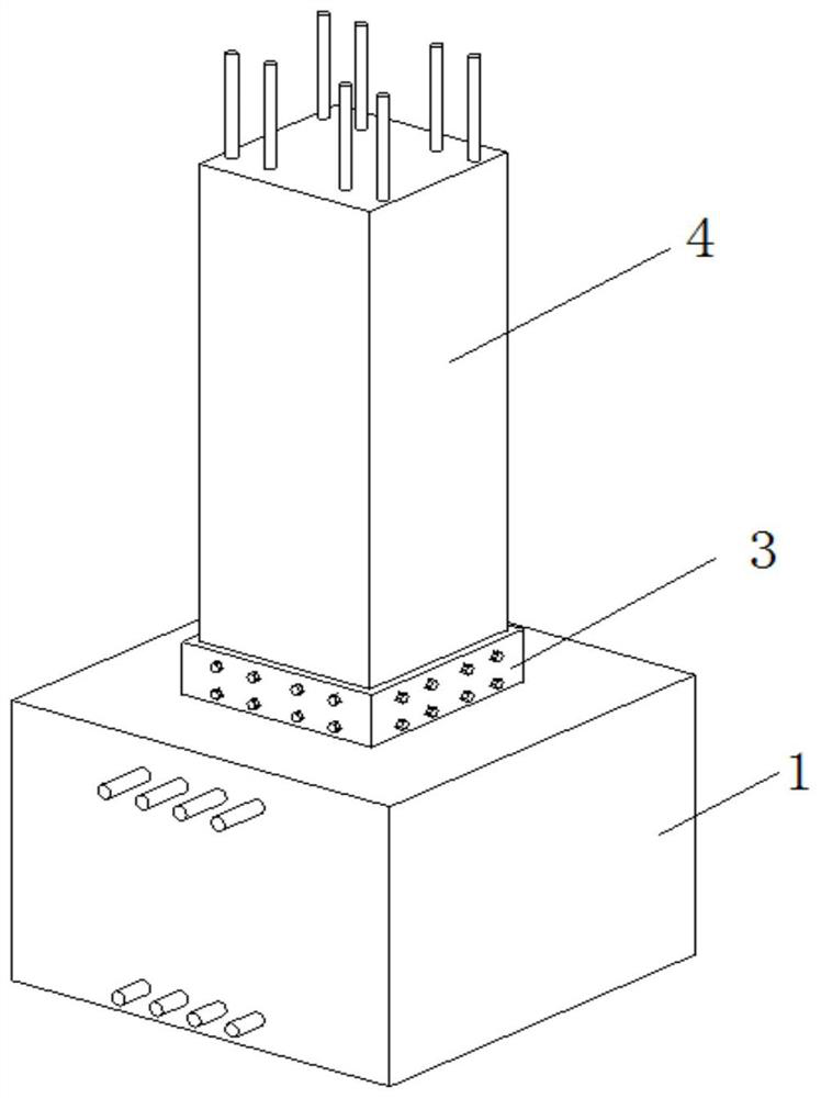
[0045] Such as figure 1 As shown, the steel-wood composite seismic pad foundation of the present invention comprises a reinforced concrete foundation 1, a composite seismic pad 2, a steel sleeve 3 and a wooden column 4;

[0046] The reinforced concrete foundation 1 is a concrete cast-in-place structure, including a lower foundation 11 and an upper foundation 12,

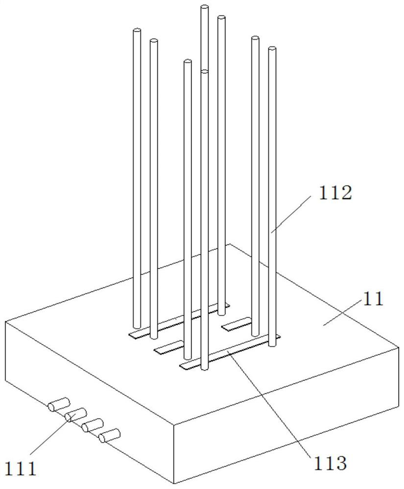
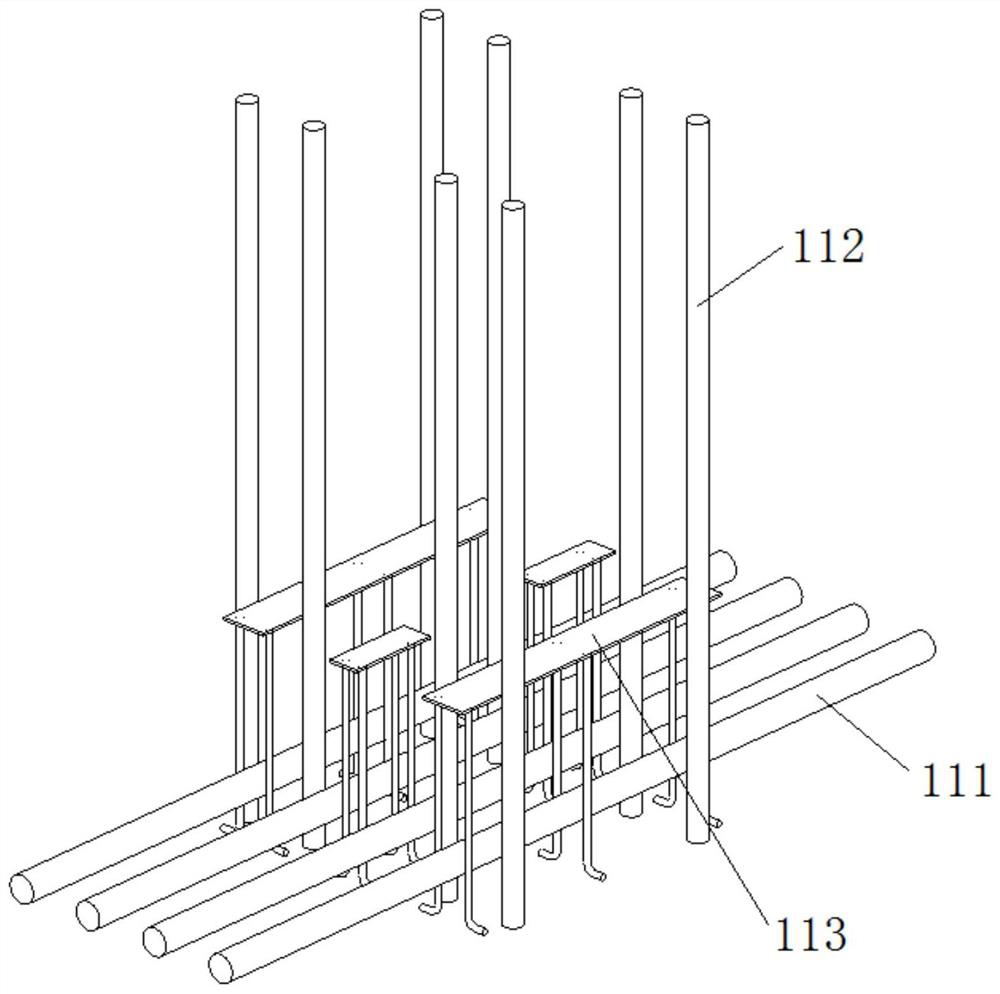
[0047] Such as Figure 2-4 As shown, the lower foundation 11 is provided with a number of horizontal steel bars I111 parallel to each other, vertical steel bars 112 and steel bar embedded parts 113, and the steel bar embedded parts include horizontal plates 1131 and π-shaped steel bars 1132 fixed on the horizontal plates, each There are 2-3 sets of π-shaped steel bars 1132 on the steel bar embedded parts, each group of π-shaped steel bars 1132 includes two symmetrical L-shaped steel bars, and the horizontal stee...


PUM


Abstract

The invention relates to the field of building construction, and discloses a steel-wood composite vibration-isolation pad foundation and an installation method thereof. The steel-wood composite vibration-isolation pad foundation includes a reinforced concrete foundation, a composite vibration-isolation pad, a steel sleeve and a wooden column; the reinforced concrete foundation Including the lower foundation and the upper foundation, the lower foundation is provided with a number of parallel horizontal steel bars I, vertical steel bars and steel embedded parts, and the combined seismic isolation pad includes an upper cover plate set from top to bottom, several inner splints and lower floors. For the cover plate, the steel sleeve is set on the outside of the combined shock-absorbing pad. The wooden column is inserted into the steel sleeve and connected with the steel sleeve by bolts. The vertical steel bar runs through the wooden column and extends out of the top of the wooden column. The invention can effectively increase the seismic energy consumption of the existing foundation structure, reduce the damage to the existing structure when the earthquake occurs, consume the seismic energy through the horizontal displacement generated by the rubber ball, increase the safety of the structure, and make the isolation through the SMA rubber bolt After the earthquake, the vibrating pad has good self-resetting performance and deformation recovery ability.

Description

technical field [0001] The invention relates to the field of building construction, in particular to a steel-wood composite foundation and an installation method for the foundation. Background technique [0002] At present, based on the reality of frequent earthquakes, the seismic fortification of buildings has received more and more attention. In architectural design, the design of anti-seismic components is related to the safety of the structure in the later stage. The seismic isolation structure has been recognized by the engineering community because of its good shock absorption effect. The working principle of the seismic isolation structure is to set a slip layer or isolation layer between the building and the foundation to prevent the seismic energy from being transmitted upwards, thereby reducing the seismic response of the structure. [0003] The existing seismic isolation systems that are relatively mature and widely used in practical engineering mainly include t...

Claims


Application Information

Patent Timeline
Patent Type & Authority Patents(China)
IPC IPC(8): E02D27/34E02D27/12E04B1/00E04B1/98E04H9/02
CPCE02D27/12E02D27/34E04B1/0007E04B1/98E04H9/021
Inventor 牟犇刘艺
Owner QINGDAO TECHNOLOGICAL UNIVERSITY
Why Eureka
Try Eureka