
Dynamic performance testing system for basic braking device

A basic braking device, dynamic performance technology, applied in braking safety systems, brakes, braking components, etc., can solve problems such as differences in real transmission efficiency

Inactive Publication Date: 2020-06-12
CRRC QIQIHAR ROLLING CO LTD
View PDF13 Cites 2 Cited by
  • Summary
  • Abstract
  • Description
  • Claims
  • Application Information

AI Technical Summary

Problems solved by technology

For a long time, the brake system design of railway freight cars in my country has been evaluated by static brake transfer efficiency. The static brake transfer efficiency is calculated by comparing the output thrust of the brake shoe (brake pad) with the air pressure of the brake cylinder when the vehicle is in a static state. As a result, although the static braking transmission efficiency can reflect the transmission efficiency of the braking force to a certain extent, there is still a large difference with the real transmission efficiency

Method used


Image

  • Dynamic performance testing system for basic braking device
  • Dynamic performance testing system for basic braking device
  • Dynamic performance testing system for basic braking device

Examples


Embodiment 1

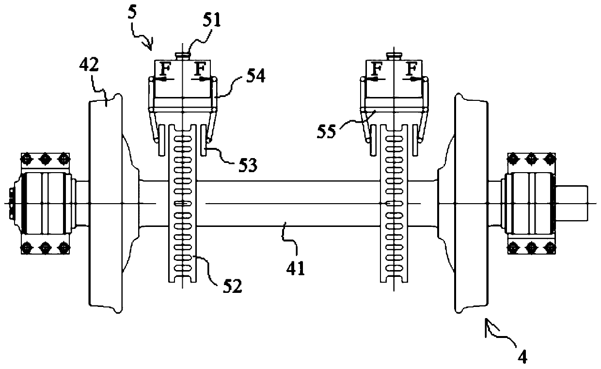
[0077] Such as Figure 10 As shown, the connecting assembly 62 may include a connecting rod 621 for connecting two opposite brake shoe assemblies 61, so as to ensure that each brake shoe assembly 61 can reliably brake the wheel surface of the wheel 42, and the two sides of the connecting rod 621 can also be Mounting seat 622 is provided, and brake shoe assembly 61 can be connected with mounting seat 622 through a suspender. The number of brake cylinders 51 can be two, and the two brake cylinders 51 interact with the two brake shoe assemblies 61 through connecting rods 621 respectively.

[0078] In this embodiment, a second sensor 512 may also be included, installed on the piston rod 511 of the brake cylinder 51, for monitoring the single-rod thrust of the piston rod 511, by comparing the single-rod thrust with that measured by the first sensor 56 The actual measured braking force can be used to calibrate the relationship between the single-rod thrust and the measured braking f...

Embodiment 2

[0080] Such as Figure 11 As shown, the connection assembly 62 may include a brake beam 623 and two mounting seats 622 opposite to each other. The brake beam 623 is used to connect the two opposite brake shoe assemblies 61, and the two ends of the brake beam 623 are respectively connected to the two sides. The mounting seat 622 forms a sliding fit. The specific sliding fit structure will not be described in detail here. The number of brake cylinders 51 can also be two, and the two brake cylinders 51 can pass through the brake beam 623 and the two brake shoe assemblies 61 respectively. interaction.

[0081] In this embodiment, a third sensor (not shown in the figure) may also be included. The third sensor may be arranged on the braking beam 623 for monitoring the thrust of the single beam. The measured braking force is compared to explore the braking force loss caused by the braking beam 623 itself and the sliding friction between the braking beam 623 and the mounting seat 622...

Embodiment 3

[0083] Such as Figure 12 As shown, the difference between the present embodiment and the second embodiment is that the number of the brake cylinder 51 is one, and the brake cylinder 51 is in drive connection with the brake beam 623 through the second brake lever 624 .

[0084] In this embodiment, a fourth sensor may also be included, and the fourth sensor is arranged on the second brake lever 624 for monitoring the thrust of the lever. The brake force loss caused behind the brake lever 624 is convenient for the subsequent improvement of the tread brake device similar to that provided in this embodiment.


PUM


Abstract

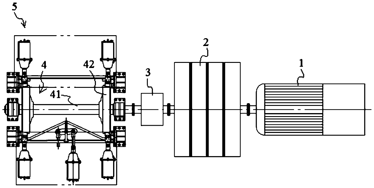
The invention discloses a dynamic performance testing system for a basic brake device. The dynamic performance testing system comprises a driving part, an inertia wheel set, a gearbox and a wheel set,and the driving part is in transmission connection with the wheel set through the inertia wheel set and the gearbox; the dynamic performance testing system further comprises a foundation braking device, the foundation braking device comprises a brake cylinder and a brake output component; and the brake cylinder is in transmission connection with the brake output component and can drive the brakeoutput component to brake the wheel set, and the brake output component is further provided with a first sensor used for monitoring the brake force of the brake output component acting on the wheel set. Such a structure, the driving part, the inertia wheel set, the gearbox and the wheel set are arranged, the actual running state of the railway vehicle can be accurately simulated, then the brakingforce output by the braking output component is monitored through the first sensor, and the braking force transmission efficiency of the basic braking device of the railway vehicle under the dynamic condition can be obtained by comparing the braking force with the air pressure of the braking cylinder.

Description

technical field [0001] The invention relates to the technical field of railway vehicle performance testing, in particular to a dynamic performance testing system of a foundation braking device. Background technique [0002] The transmission efficiency of the foundation braking device of railway vehicles such as railway wagons is one of the key parameters in the evaluation of the design of the braking system. For a long time, the brake system design of railway freight cars in my country has been evaluated by static brake transfer efficiency. The static brake transfer efficiency is calculated by comparing the output thrust of the brake shoe (brake pad) with the air pressure of the brake cylinder when the vehicle is in a static state. As a result, although the static braking transmission efficiency can reflect the transmission efficiency of the braking force to a certain extent, there is still a large difference with the real transmission efficiency. [0003] Therefore, how to ...

Claims


Application Information

Patent Timeline
Patent Type & Authority Applications(China)
IPC IPC(8): B60T17/22
CPCB60T17/228
Inventor 任玉玺刘新王俊龙安世龙杨淼汉雷牛伟力
Owner CRRC QIQIHAR ROLLING CO LTD
Learn More