Burr removing equipment for motor barrel

A burr removal and erection technology, which is applied to metal processing equipment, parts of grinding machine tools, grinding/polishing equipment, etc., can solve problems such as increased labor costs and long burrs, and achieve the effect of improving practicability

Active Publication Date: 2020-06-12
TAIZHOU SHENG WORLD MECHANICS
View PDF9 Cites 0 Cited by
  • Summary
  • Abstract
  • Description
  • Claims
  • Application Information

AI Technical Summary

Problems solved by technology

[0002] After the motor barrel is produced, due to the production process and other reasons, there are many burrs on the surface of the motor barrel, so it needs to go through multiple steps to remove the burrs. The traditional manual deburring is long and increases the labor cost.

Method used


Image

  • Burr removing equipment for motor barrel
  • Burr removing equipment for motor barrel
  • Burr removing equipment for motor barrel

Examples


Embodiment Construction

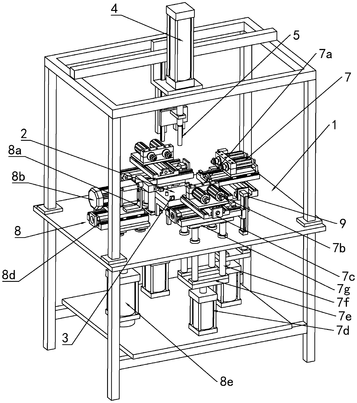
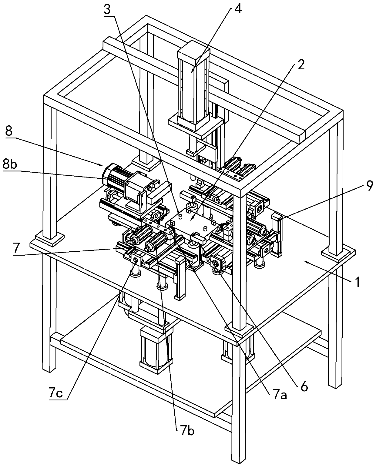
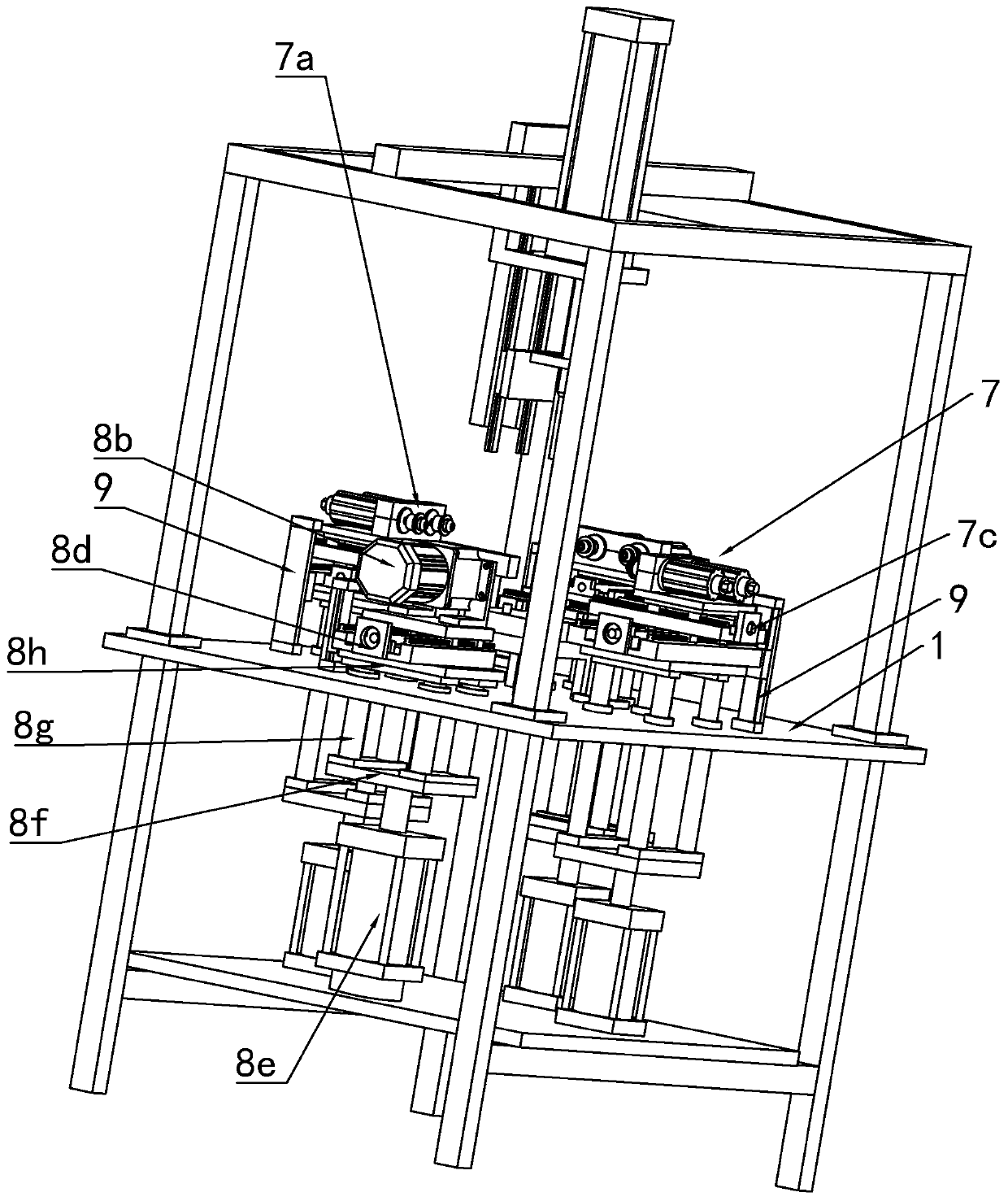
[0027] refer to Figure 1 to Figure 4 An embodiment of the present invention will be further described.

[0028] A deburring machine for a motor cylinder, comprising a support table 1, the middle part of the support table 1 is provided with a mounting seat 2 for placing a power supply machine barrel, and several columns 3 are provided at the upper end of the mounting seat 2, wherein the mounting seat 2 is detachable and replaceable; a support frame 4 is set up on the support platform 1, and a first drive cylinder with the driving end facing downward is arranged on the support frame 4 directly above the mounting seat 2, and the first drive cylinder On the driving end of the cylinder, there is a lower pressing rod 5; on both sides of the mounting seat 2, there are rotary clamping cylinders 6; Three first stations 7 and one second station 8. Wherein the cross-section of the mounting seat 2 is rectangular, and the number of rotary clamping cylinders 6 is two, which are arranged ...


PUM


Abstract

The invention discloses burr removing equipment for a motor barrel. The burr removing equipment for the motor barrel comprises a supporting table, a mounting seat for allowing the motor barrel to be placed is arranged in the middle of the supporting table, a plurality of stand columns are arranged at the upper end of the mounting seat, wherein the mounting seat is detachably replaceable, a supporting frame is erected on the supporting table, a first driving cylinder with a driving end facing downwards is arranged at the position, located right above the mounting seat, on the supporting frame,a downward pressing rod is arranged at the driving end of the first driving cylinder, rotary clamping air cylinders are arranged on the two sides of the mounting seat, three first stations and a second station which are uniformly distributed along the circumference are arranged at the position, on the periphery of the mounting seat, on the supporting table, the section of the mounting seat is in aregular rectangle shape, the number of the rotary clamping air cylinders is two, and the two rotary clamping air cylinders are arranged at the two diagonal positions of the rectangular mounting seat.

Description

technical field [0001] The invention belongs to the technical field of motor manufacturing, in particular to a device for removing burrs from motor cylinders. Background technique [0002] After the motor barrel is produced, due to the production process and other reasons, there are many burrs on the surface of the motor barrel, so it needs to go through multiple steps to remove the burrs, and the traditional manual deburring is long and increases the labor cost. Contents of the invention [0003] Aiming at the deficiencies in the prior art, the purpose of the present invention is to provide a deburring machine which has a simple structure and can efficiently remove the burrs on the motor barrel. [0004] In order to achieve the above object, the present invention provides the following technical solutions: a deburring machine for motor cylinders, including a support platform, the middle part of the support platform is provided with a mounting base for placing the power su...

Claims


Application Information

Patent Timeline
Patent Type & Authority Applications(China)
IPC IPC(8): B24B9/00B24B41/04B24B41/06B24B51/00B23D79/02B23Q3/06
CPCB23D79/02B23Q3/06B24B9/00B24B41/04B24B41/06B24B51/00
Inventor 李文
Owner TAIZHOU SHENG WORLD MECHANICS
Why Eureka
Try Eureka