
Current-limiting protection device and motor driving chip

A current-limiting protection and circuit technology, applied in the field of current-limiting protection devices and motor drive chips, can solve problems such as increased resistance loss, increased circuit design cost, complex duty cycle, etc., to reduce design requirements, reduce development costs, and reduce The effect of motor drive losses

Active Publication Date: 2020-06-09
小华半导体有限公司
View PDF14 Cites 1 Cited by
  • Summary
  • Abstract
  • Description
  • Claims
  • Application Information

AI Technical Summary

Problems solved by technology

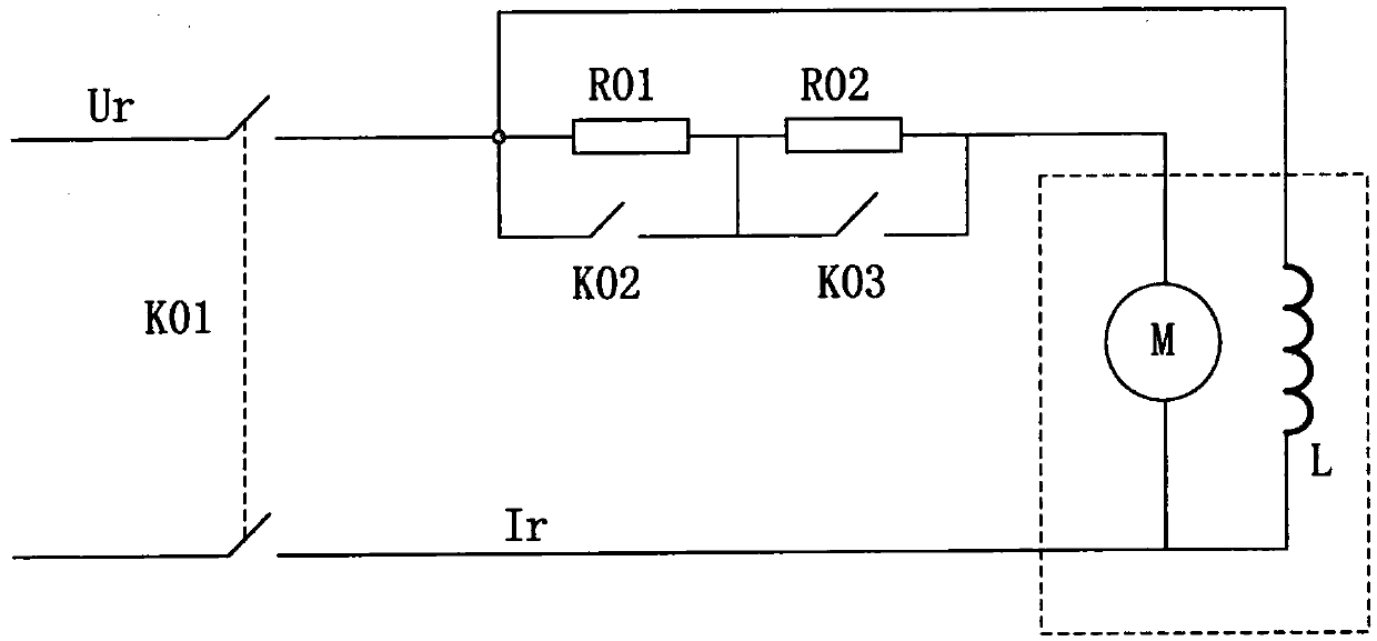
[0004] However, the disadvantages of the above-mentioned prior art are: 1. In the armature circuit series resistance starting scheme, the circuit needs external components such as resistors and switches, which increases the cost of circuit design. At the same time, increasing the resistance element will inevitably increase the loss on the resistance
2. Relying on changing the PWM duty cycle of the drive signal to reduce the voltage. In the starting scheme, it is necessary to design a PWM signal with a complex duty cycle, and it is necessary to judge when the start-up ends, which increases the difficulty of designing the overall circuit.

Method used


Image

  • Current-limiting protection device and motor driving chip
  • Current-limiting protection device and motor driving chip
  • Current-limiting protection device and motor driving chip

Examples


Embodiment Construction

[0029] Several technical features and advantageous details of the disclosure are explained more fully with reference to the non-limiting embodiments illustrated in the drawings and detailed in the following description. Also, the following description omits descriptions of well-known raw materials, processing techniques, components, and equipment so as not to unnecessarily obscure the technical gist of the present disclosure. However, those skilled in the art will understand that, in describing the embodiments of the present disclosure hereinafter, the description and specific examples are given by way of illustration only and not limitation.

[0030] Wherever possible, the same numbers will be used throughout the drawings to refer to the same or like parts. In addition, although the terms used in the present disclosure are selected from well-known and commonly used terms, some terms mentioned in the specification of the present disclosure may be selected by the discloser at h...


PUM


Abstract

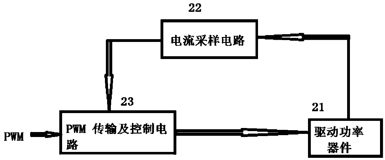
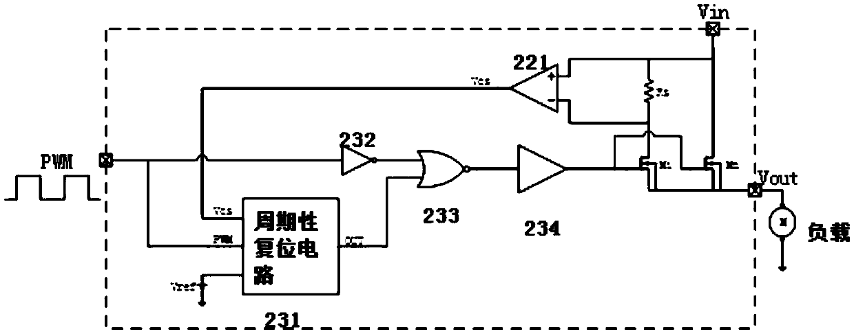
A current-limiting protection device comprises a current sampling circuit which is connected with a driving power device and is used for sampling the current of a load and converting a sampling current signal into a sampling output voltage signal, and a PWM signal transmission and control circuit which is in signal connection with the current sampling circuit and the PWM and is used for controlling the driving power device to be turned on or turned off according to a comparison result of the sampling output voltage and a reference voltage. According to the scheme of the invention, the current-limiting protection device is integrated in the motor driving chip, peripheral elements such as an armature series resistor and a switching tube for starting the motor are omitted, and the developmentcost and the motor driving loss are reduced. Moreover, the starting current is controlled by sampling the current of the power tube cycle by cycle, the current-limiting starting function of the motorcan be realized without changing the duty ratio of the preset PWM signal, and the current-limiting function of the device is automatically stopped after the motor is started, so that the normal transmission of the preset PWM control signal is not influenced.

Description

technical field [0001] The invention relates to the technical field of motors, in particular to a current limiting protection device and a motor drive chip. Background technique [0002] In the motor drive, such as the starting stage of a DC motor, since the motor speed is 0, the corresponding electromotive force e of the armature of the motor is also 0. If the applied voltage is the rated voltage Vin, considering that the armature resistance Ra is small, the voltage balance equation It can be seen that the starting current will be relatively large, generally speaking, the starting current can reach 10 to 20 times the rated current. Such a high start-up current may cause overheating of the driving power switch tube, thereby damaging the power switch tube, and such a large current impact may cause an instantaneous drop in the power supply voltage, thereby affecting the normal operation of other circuits around the power grid. Therefore, the usual solution is to use a curre...

Claims


Application Information

Patent Timeline
Patent Type & Authority Applications(China)
IPC IPC(8): H02H9/02H02P1/18
CPCH02H9/025H02P1/18
Inventor 张进贺刘慧明
Owner 小华半导体有限公司
Learn More