A positioning device for fuel cell stack assembly

A fuel cell stack and positioning device technology, which is applied to fuel cells, circuits, electrical components, etc., can solve problems such as stack dislocation, column deformation, and thin positioning rods, so as to reduce assembly difficulty, facilitate processing, and improve stability and reliability. safety effect

Active Publication Date: 2021-01-15
DALIAN INST OF CHEM PHYSICS CHINESE ACAD OF SCI
View PDF10 Cites 1 Cited by
  • Summary
  • Abstract
  • Description
  • Claims
  • Application Information

AI Technical Summary

Problems solved by technology

Internal positioning is to set positioning holes on the edge of the bipolar plate and MEA, and to achieve positioning through positioning rods passing through the positioning holes. For example, the Chinese invention patent application specification with publication number CN103633359A discloses a fuel cell stack assembly method. This is achieved by restricting the four corners of the stack components with a column, but the aperture of this positioning is small, the positioning rod is thin, and the column is prone to deformation when squeezed, resulting in a certain misalignment of the stack when the stack is assembled; external positioning In order to define each outer surface of the stack through a certain fixing device, for example, the Chinese invention patent application publication number CN 105428688 A discloses a fuel cell stack assembly method by providing a fixing mechanism and a positioning mechanism, but the method requires The bipolar plate of each component of the stack is exactly the same size as the MEA, which has certain limitations

Method used


Image

  • A positioning device for fuel cell stack assembly
  • A positioning device for fuel cell stack assembly
  • A positioning device for fuel cell stack assembly

Examples


Embodiment 1

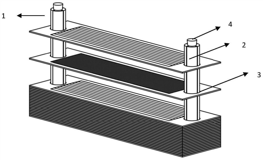
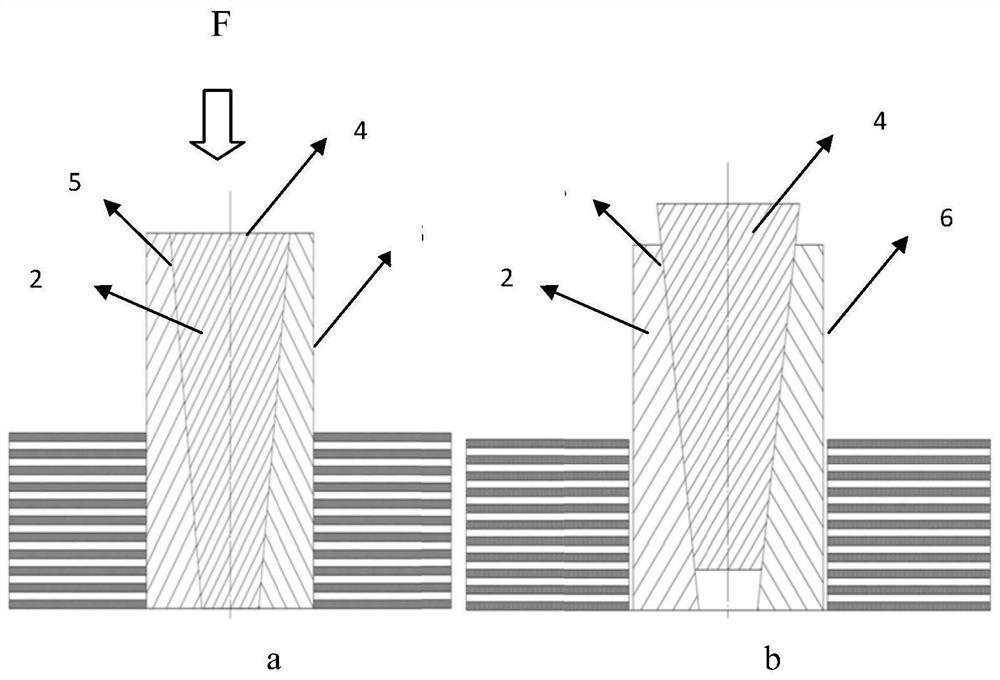
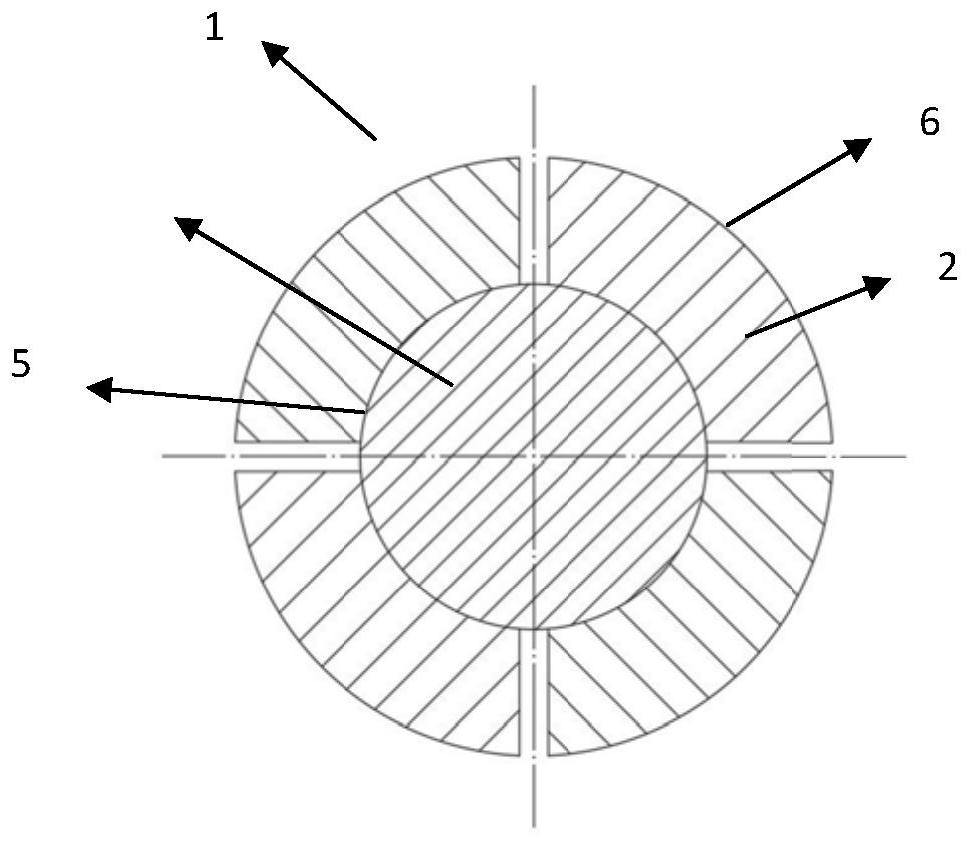
[0020] In this example, if figure 1 with figure 2 , image 3 As shown, the positioning device 1 is divided into two functional parts, the first functional part is a supporting body located on the peripheral side, and the supporting body is assembled from four supporting parts 2 in the radial direction; the second functional part is a core located in the center body 4; the shape of the outer peripheral surface 6 of the support body is exactly the same as the shape of the inner peripheral surface of the electric stack public cavity 3 .

[0021] Such as figure 2 As shown, the outer peripheral surface of the support body matches the inner peripheral surface structure of the public cavity, and the outer diameter of the support body (that is, the outer edge size of the support body) is slightly smaller than the inner diameter (that is, the inner edge size) of the fuel cell stack public cavity. Size), preferably 1-5mm, so that the internal positioning device can be placed in the...


PUM


Abstract

The positioning device for assembling the fuel cell stack is an inner positioning device of which the size can be finely adjusted. The positioning device is divided into two parts, namely a supportingmodule and a core body. When the stack is assembled, the inner positioning devices are respectively placed in a common cavity (an air cavity or a water cavity) of the stack, so that an end plate, a bipolar plate, a current collecting plate, a membrane electrode and the like of the stack can be smoothly superposed, and after the superposition of stack components such as the bipolar plate and the current collecting plate is finished, an oil press is used for pressing and the stack is fastened and locked; and the core body of the inner positioning device is taken out, and then the supporting module is taken out to finish the assembly of the stack. The device is simple and flexible in structure, fuel cell stacks of different specifications can be assembled by adjusting the shape and the length of the inner positioning device, the assembly alignment degree of the fuel cell stacks is accurate, and the stability and the safety of the fuel cell stacks are improved.

Description

technical field [0001] The invention relates to the technical field of fuel cells, in particular to a positioning device for assembling a fuel cell stack. Background technique [0002] A fuel cell is a device that directly uses hydrogen energy to generate electricity. The chemical energy of hydrogen and oxygen is directly converted into electrical energy. Since it does not go through the Carnot cycle, the energy conversion rate is high; the fuel cell is environmentally friendly, and the only emission is water. Therefore, fuel cell technology is considered to be the preferred clean and efficient power generation technology in the 21st century. [0003] The fuel cell stack is composed of multiple single cells. The stack needs to have a positioning device during assembly. The positioning device ensures that the components of the stack will not be misaligned during assembly. If the positioning fails, it will cause uneven force on the fuel cell stack. , affect the sealing and ev...

Claims


Application Information

Patent Timeline
Patent Type & Authority Patents(China)
IPC IPC(8): H01M8/2475
CPCH01M8/2475Y02E60/50
Inventor 郑利民侯明艾军洪有陆邵志刚
Owner DALIAN INST OF CHEM PHYSICS CHINESE ACAD OF SCI
Why Eureka
Try Eureka