Positioning device and fuel cell stack assembling method

A fuel cell stack and positioning device technology, which is applied to fuel cells, circuits, electrical components, etc., can solve the problems of high friction between the positioning rod and the positioning hole, easy contact with the positioning hole, and difficulty in pulling out the positioning rod. Easy to operate, improve assembly accuracy and efficiency, simple and reliable structure

Pending Publication Date: 2022-08-02
上海安池科技有限公司
View PDF1 Cites 2 Cited by
  • Summary
  • Abstract
  • Description
  • Claims
  • Application Information

AI Technical Summary

Problems solved by technology

However, the positioning hole of this positioning method is small, the stack is long, and the deflection of the slender rod is relatively large, which is prone to bending deformation
In addition, due to the superimposed tolerance of the multilayer film electrode and the bipolar plate, the friction between the positioning rod and the positioning hole is very large, which brings great difficulties to the pulling out of the positioning rod after the assembly is completed.
At the same time, the large frictional force generated between the existing positioning rod and the positioning hole is easy to deform the bipolar plate, and then the positioning holes at two adjacent positions are prone to contact, resulting in a short circuit, and may even be burned in severe cases. stack, resulting in a greater safety hazard

Method used


Image

  • Positioning device and fuel cell stack assembling method
  • Positioning device and fuel cell stack assembling method
  • Positioning device and fuel cell stack assembling method

Examples


Embodiment Construction

[0055] The technical solutions in the embodiments of the present application will be clearly and completely described below with reference to the accompanying drawings in the embodiments of the present application. Obviously, the described embodiments are part of the embodiments of the present application, not all of the embodiments. Based on the embodiments in the present application, all other embodiments obtained by those of ordinary skill in the art without creative work fall within the protection scope of the present application.

[0056] Those skilled in the art understand that, as stated in the background art, the existing positioning devices for fuel cell stack assembly still have more or less defects, and there is still a need for improvement. For example, the Chinese Patent Publication No. CN111261918A proposes an internal positioning structure, which uses a positioning device with adjustable size to position the common chamber to realize stack positioning and assembl...


PUM


Abstract

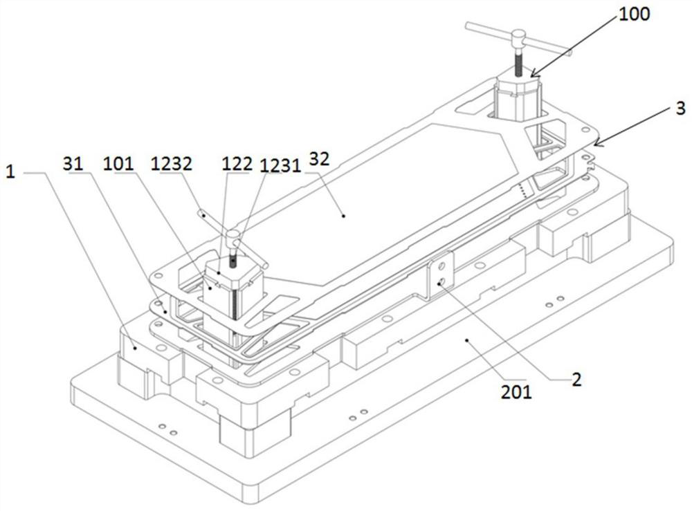
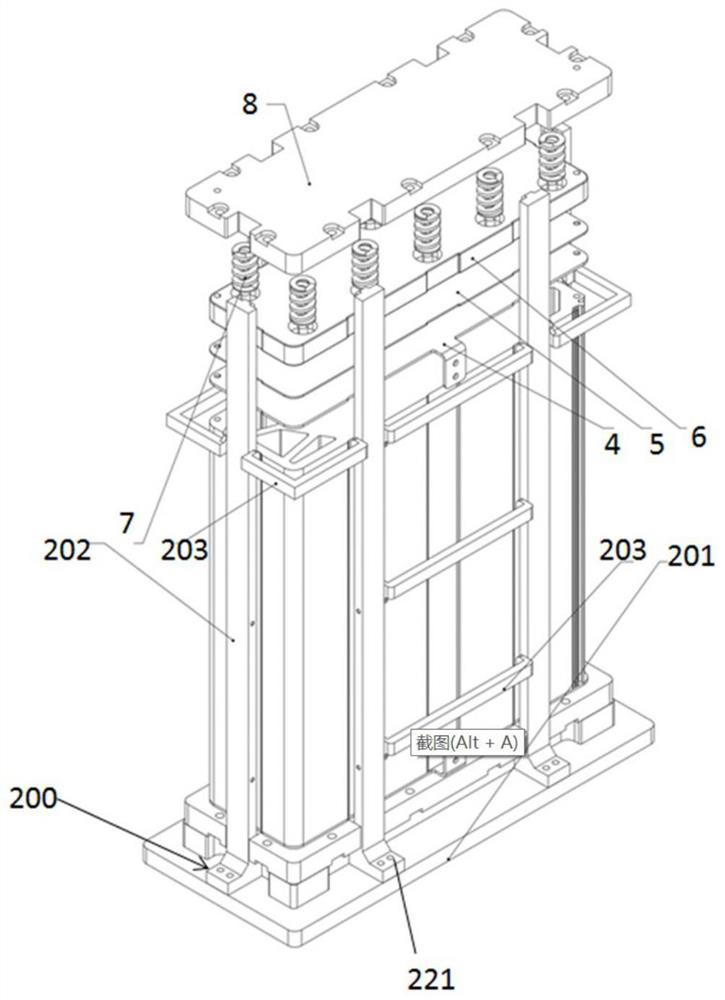
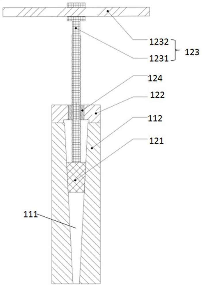
The invention discloses a positioning device and an assembling method of a fuel cell stack, and belongs to the technical field of fuel cells. A positioning device is used for assembling a fuel cell stack, the fuel cell stack comprises a first end plate, a first collector plate, a stack main body, a second collector plate and a second end plate, the first end plate, the first collector plate and the stack main body are provided with a common cavity, the positioning device comprises: an inner positioning assembly, the inner positioning assembly comprises a support body and a motion connection mechanism, the movement connecting mechanism is suitable for moving in the channel of the support body, so that the support body expands outwards in the radial direction to be in an expansion state, and the support body in the expansion state is matched with the public cavity and is used for positioning the first end plate, the first collector plate and the electric pile main body; and the outer positioning assembly comprises a base, a limiting frame and a plurality of positioning rods and is used for positioning the second collector plate and the second end plate. The assembly precision of the fuel cell stack can be improved, and the safety of the fuel cell is improved.

Description

technical field [0001] The present application belongs to the technical field of fuel cells, and in particular relates to a positioning device and a method for assembling a fuel cell stack. Background technique [0002] A fuel cell is an electrochemical device that directly converts the chemical energy of fuel into electrical energy, and proton exchange membrane fuel cell (PEMFC) is one of them. Generally, the main body of the fuel cell stack is composed of several membrane electrodes and bipolar plates stacked alternately. In addition, the fuel cell stack also includes end plates at both ends, current collector plates and other components. In recent years, with the development of science and technology and the improvement of technology, the power demand of fuel cells is also increasing, and the number of battery cells is also increasing. When assembling the fuel cell stack, a positioning device needs to be provided to ensure the assembly accuracy of each component in the s...

Claims


Application Information

Patent Timeline
Patent Type & Authority Applications(China)
IPC IPC(8): H01M8/2404H01M8/247H01M8/2475
CPCH01M8/2404H01M8/247H01M8/2475Y02E60/50
Inventor 申德李玉平张旭
Owner 上海安池科技有限公司
Why Eureka
Try Eureka