
Choke area identification method and equipment

An identification method and wind blocking technology, applied in the field of wind power, can solve the problems of the range of the wind blocking area and the deviation of wind speed, the inability to provide reference for the design of wind measurement schemes, and the occupation of many computing resources.

Pending Publication Date: 2020-06-09
BEIJING GOLDWIND SCI & CREATION WINDPOWER EQUIP
View PDF0 Cites 0 Cited by
  • Summary
  • Abstract
  • Description
  • Claims
  • Application Information

AI Technical Summary

Problems solved by technology

[0003] However, there are many problems in using the CFD method to identify the risk of the wind-blocking area.
Specifically, the input information of existing technical schemes includes terrain data, observation results of wind measuring towers, etc., and the risk identification of wind-blocking areas is usually carried out in the stage of micro-site selection, but it cannot provide reference for the design of wind measuring schemes. At present, the There is a lack of standards and methods for the representative judgment of the wind measuring tower in the wind blocking area
In addition, the calculation results of the CFD method will be affected by boundary conditions, air parameters, physical models, etc., so the CFD method is not accurate in evaluating the blocking effect of high-altitude terrain on the air in the meteorological environment, and it is not accurate for wind blocking There is a certain deviation in the judgment of the area range and wind speed
In addition, the CFD method obtains the calculation results of the flow field by solving the N-S equation, which has the problems of slow calculation speed and large calculation resources

Method used


Image

  • Choke area identification method and equipment
  • Choke area identification method and equipment
  • Choke area identification method and equipment

Examples


Embodiment Construction

[0046] Reference will now be made in detail to the exemplary embodiments of the present disclosure, examples of which are illustrated in the accompanying drawings, wherein like numerals refer to like parts throughout. The embodiments are described below in order to explain the present invention by referring to the figures. Apparently, the described embodiments are only some of the embodiments of the present disclosure, but not all of them.

[0047] In the present disclosure, terms including ordinal numbers such as 'first', 'second', etc. may be used to describe various elements, but the elements should not be construed as being limited by these terms. These terms are only used to distinguish one element from other elements. For example, a first element could be termed a second element and vice versa without departing from the scope of the present disclosure.

[0048] Before the detailed description, the technical terms involved in the disclosure are described to facilitate t...


PUM


Abstract

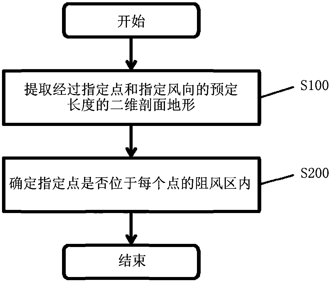
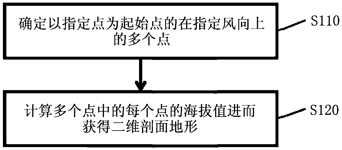
The invention provides a choke area identification method and equipment. The method comprises that: a two-dimensional profile terrain with a predetermined length passing through a specified point anda specified wind direction from terrain data is extracted according to the input specified point and the specified wind direction; and, for each point within a predetermined range on the two-dimensional profile terrain, a predetermined multiple of a difference between altitude values of the each point and the specified point is compared with a horizontal distance between the specified point and the each point to determine whether the specified point is located within a choke region of the each point.

Description

technical field [0001] The invention relates to the field of wind power, and more specifically, to a method and equipment for identifying a wind blocking area. Background technique [0002] The wind blocking area risk identification technology is a technology to identify the areas in the selected wind field whose wind conditions are affected by the blockage of high altitude locations. At present, the risk identification of the wind blocking area mainly relies on the CFD method, that is, by using the CFD method to calculate the wind conditions of the whole field according to the terrain and the observation data of the wind measuring tower, and then obtain the distribution of the wind parameters in the field, and then according to the obtained wind parameters To comprehensively judge whether the selected point is in the wind blocking area. [0003] However, there are many problems in using CFD method to identify the risk of the wind-blocking area. Specifically, the input inf...

Claims


Application Information

Patent Timeline
IPC IPC(8): G06Q10/06G06Q50/06
CPCG06Q10/0639G06Q50/06
Inventor 李小兵苏文华许小龙
Owner BEIJING GOLDWIND SCI & CREATION WINDPOWER EQUIP
Learn More