
IGBT module solder layer fatigue aging failure simulation method based on voidage

A simulation method and technology of solder layer, which is applied in the field of fatigue aging simulation of IGBT module solder layer based on void ratio, can solve the problem of unclear influence mechanism of IGBT module reliability, inability to qualitatively and quantitatively analyze electromechanical thermal stress and reliability influence, and inability to evaluate Solder layer IGBT module reliability issues and other issues, to achieve the effect of improving accuracy

Pending Publication Date: 2020-06-09
CHONGQING UNIV
View PDF0 Cites 4 Cited by
  • Summary
  • Abstract
  • Description
  • Claims
  • Application Information

AI Technical Summary

Problems solved by technology

[0003] Most of the existing studies on fatigue failure and reliability of IGBT modules are based on the results of power cycle experiments or temperature cycle experiments. This method is often unable to qualitatively and quantitatively analyze the influence of solder layer fatigue aging on the electromechanical thermal stress and reliability of the IGBT module. The influence of the fatigue aging failure evolution process of the solder layer on the electrothermal stress and reliability of the IGBT module is ignored, resulting in the unknown mechanism of the fatigue aging failure process of the solder layer on the reliability of the IGBT module
Based on this background, the present invention proposes a method for simulating the fatigue aging failure of the IGBT module solder layer based on the change of the void rate in view of the problem that the existing method cannot evaluate the reliable influence of the solder layer on the IGBT module in different stages of fatigue failure.

Method used


Image

  • IGBT module solder layer fatigue aging failure simulation method based on voidage
  • IGBT module solder layer fatigue aging failure simulation method based on voidage
  • IGBT module solder layer fatigue aging failure simulation method based on voidage

Examples


Embodiment 1

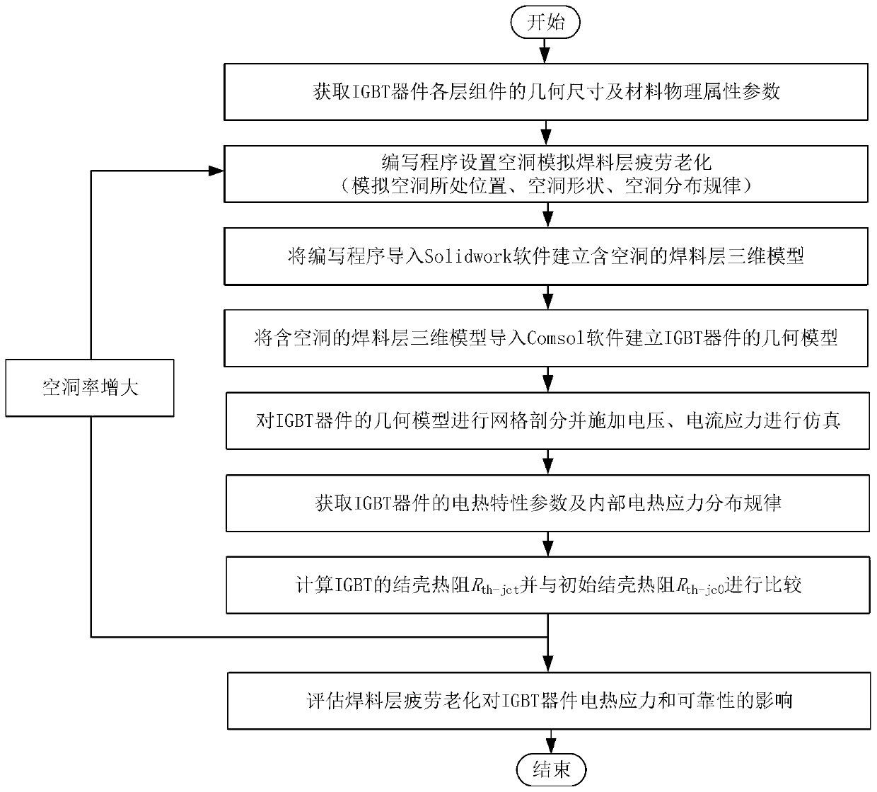
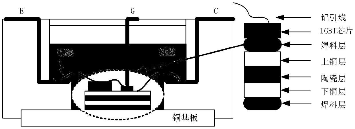
[0032] figure 1 It is a flow chart of the simulation method for the fatigue aging failure of the IGBT module solder layer, figure 2 is a schematic diagram of the cross-sectional structure of the IGBT module, image 3 It is a schematic diagram of the simulation that the voids are concentrated in different regions of the solder layer, Figure 4 It is a schematic diagram of the simulation under different fatigue aging failure states of the solder layer. in:

[0033] 1. a simulation method of fatigue aging failure of IGBT module solder layer, it is characterized in that comprising the following steps:

[0034] 1) Obtain the geometric dimensions of the components of each layer of the IGBT module and the physical property parameters of the materials of each layer, and write a program to set the voids to simulate the fatigue aging failure process of the solder layer (set the voids at different positions, different void shapes, void distribution areas, and void rates) , and impor...


PUM


Abstract

The invention relates to an IGBT module solder layer fatigue aging failure simulation method based on voidage, and belongs to the technical field of semiconductors. The method comprises the followingsteps: firstly, acquiring geometric dimensions and material physical attribute parameters of each layer of assembly of the IGBT module, and simulating a fatigue aging failure process of a cavity simulation solder layer; importing the simulation process into Solidwork software to establish a solder layer three-dimensional model containing a cavity; secondly, importing the three-dimensional model ofthe solder layer into Comsol software to establish a geometric model of the IGBT device, and performing mesh generation on the geometric model of the IGBT device; then, voltage and current stresses of actual working conditions are equivalent and applied to an IGBT device for mechanical-thermoelectric multi-coupling field simulation; and finally, evaluating the influence of fatigue aging of the solder layer on the reliability of the IGBT device. According to the method, the failure evolution process of fatigue aging of the solder layer is considered, and the accuracy of reliability evaluationof the IGBT module is improved.

Description

technical field [0001] The invention belongs to the technical field of semiconductors, and relates to a method for simulating fatigue aging failure of an IGBT module solder layer based on void ratio. Background technique [0002] In the IGBT module, due to the cyclical alternating thermal stress generated during the operation of the device, the solder layer of the IGBT is fatigued and aged, which is likely to cause the failure of the IGBT module, resulting in the shutdown of the power conversion device, affecting the safety and reliability of the power system and industrial control system. sex. Although the design process improvement and packaging optimization of the IGBT chip can improve the reliability of the IGBT module, the fatigue aging of the solder layer of the IGBT module is inevitable during use. Therefore, simulate the fatigue aging failure process of the solder layer, analyze the influence of solder layer aging on the electrothermal stress and reliability inside ...

Claims


Application Information

Patent Timeline
Patent Type & Authority Applications(China)
IPC IPC(8): G06F30/23G06F111/10G06F119/14
Inventor 李辉龙海洋姚然王晓赖伟于仁泽刘人宽刘晓宇李金元
Owner CHONGQING UNIV
Learn More