A hedging energy dissipation type debris flow diversion system
A shunt system and mud-rock flow technology, applied in construction, artificial waterways, water conservancy projects, etc., can solve the problems of unsatisfactory prevention and control of mud-rock flow, and achieve the effect of strong anti-geological disaster ability, reduced impact force and destructive effect
- Summary
- Abstract
- Description
- Claims
- Application Information
AI Technical Summary
Problems solved by technology
Method used
Image
Examples
Embodiment 1
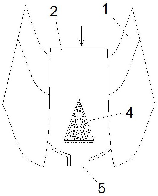
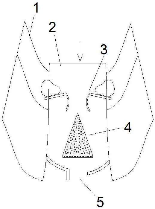
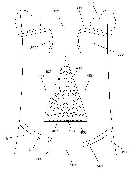
[0036] Such as figure 1 and 3 As shown, a hedging energy dissipation debris flow diversion system, the diversion system is set in the debris flow channel 2 formed between the highlands 1 on both sides, the diversion system includes a diversion dam 4 and a hedge guide device 5, wherein the The diverter dam 4 includes a semi-conical first dam body 401 arranged in the middle of the debris flow channel 2, and the tip of the semi-conical shape faces the direction of the debris flow, thereby forming two first diverter channels 405 on both sides thereof;
[0037] The counter guide device 5 includes a first arc-shaped guide dam 501 and a second arc-shaped guide dam 502 respectively arranged in front of the flow direction of the two first branch channels 405, wherein the first arc-shaped guide dam 501 and the second arc-shaped guide dam 501 Shaped guide dams 502 are arranged obliquely on both sides of the debris flow channel 2, and the first arc-shaped guide dam 501 and the second arc...
Embodiment 2
[0045] This embodiment is an improvement made on the basis of Embodiment 1, its basic structure is the same as that of Embodiment 1, and the improvements are as follows: Figure 6 As shown, the two sides of the middle part of the first dam body 401 are symmetrically provided with an impact deflection plate 407, and the free end of the impact deflection plate 407 is inclined to extend upstream, and its free end is in contact with the side of the debris flow channel 2. There is a gap, so that the debris flow of the first diversion channel 405 impacts on the impact redirection plate 407 and then changes direction and slows down again, thereby forming a silting zone between its upstream surface and the side wall of the first dam body 401, A stagnation zone is formed on its back water surface and the side wall of the first dam body 401 .
Embodiment 3
[0047] This embodiment is an improvement made on the basis of Embodiment 2, its basic structure is the same as that of Embodiment 2, and the improvements are as follows: Figure 7 As shown, the two sides of the rear part of the first dam body 401 are symmetrically provided with a secondary splitter plate 408, the secondary splitter plate 408 is V-shaped distributed along the debris flow direction, and its upstream end is connected to the impact redirection plate 407. There is a gap between the free ends to form a flow channel, and another flow channel is formed between the upstream end and the side of the debris flow channel 2; the V-shaped tip of the secondary splitter plate 408 is positioned at the side of the debris flow channel 2, thereby A debris flow deceleration zone 409 with two large ends and a small middle portion is formed between the secondary splitter plate 408 and the high ground 1 on this side.
[0048] In this embodiment, the upstream end of the secondary diver...
PUM
 Abstract
Description
Claims
Application Information
 - R&D
- Intellectual Property
- Life Sciences
- Materials
- Tech Scout
- Unparalleled Data Quality
- Higher Quality Content
- 60% Fewer Hallucinations
Browse by: Latest US Patents, China's latest patents, Technical Efficacy Thesaurus, Application Domain, Technology Topic, Popular Technical Reports.
© 2025 PatSnap. All rights reserved.Legal|Privacy policy|Modern Slavery Act Transparency Statement|Sitemap|About US| Contact US: help@patsnap.com


