
A prefabricated component forming mold

A technology for forming molds and prefabricated components, which is applied in the direction of manufacturing tools, forming indenters, ceramic molding machines, etc., and can solve problems such as loose mold bonding, low vibration effect, and difficult cleaning of concrete

Active Publication Date: 2021-08-13
中山市粤华混凝土有限公司
View PDF11 Cites 0 Cited by
  • Summary
  • Abstract
  • Description
  • Claims
  • Application Information

AI Technical Summary

Problems solved by technology

[0008] In order to overcome the limited vibrating range of the vibrating device in the prior art, the present invention cannot completely discharge the air in the concrete, which will cause the vibrating device to have a low vibrating effect on the concrete, and there are still air bubbles in the concrete, forming mold inside The combination is not tight, and there is a danger of cracking at any time. The concrete falls rapidly and splashes out of the mold due to gravity, which is a waste of resources and the splashed concrete is difficult to clean. In severe cases, the rapid fall of the concrete will deform and crack the mold, and damage the machine, concrete and the inner wall of the mold. The edge fit is not tight, so that a lot of air enters the concrete, and when the concrete is made into a mold, the surface will produce honeycomb pockmarks. The technical problem to be solved by the present invention is to provide a prefabricated component molding mold

Method used


Image

  • A prefabricated component forming mold
  • A prefabricated component forming mold
  • A prefabricated component forming mold

Examples


Embodiment

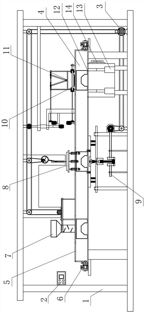
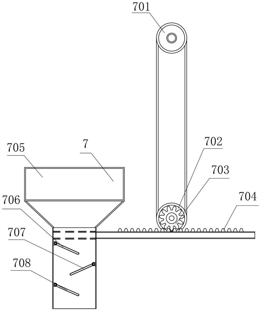
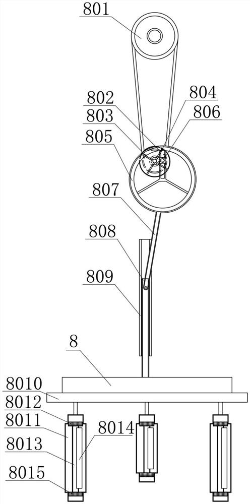
[0030] A prefabricated component forming mold, such as Figure 1-6 As shown, including the support frame 1, the control screen 2, the motor 3, the transport tube 4, the cover plate 5, the air pump 6, the feed mechanism 7, a variable ray vibration mechanism 8, the vibrating table 9, the stall mechanism 10, compaction The mechanism 11, the lifting plate 12, the first electric push rod 13 and the discharge port 14; the upper left end in the support frame 1 is provided above the upper left end, the motor 3 is provided on the right side of the bottom end of the support frame 1; the center of the support frame 1 The transport tube 4 is provided; an additive mechanism 7 is provided above the left side in the support frame 1, and the bottom of the feed mechanism 7 is connected to the transport tube 4; a variable ray vibration mechanism 8 is provided in the top of the support frame 1, and a variable speed The upper left end of the vibrating mechanism 8 is connected to the feed mechanism 7; ...


PUM


Abstract

The invention relates to a prefabricated component, in particular to a prefabricated component molding die. The technical problem to be solved by the present invention is to provide a mold for forming a prefabricated component. A prefabricated component forming mold, including a support frame, a control panel, a motor, a transport pipe, a cover plate, an air pump, a feeding mechanism, a variable-speed vibrating mechanism, a vibrating table, a flattening mechanism, a compacting mechanism, a lifting plate, the first An electric push rod and a discharge port; a control panel is arranged above the middle of the left end of the support frame; a motor is arranged on the right side of the bottom end of the support frame. The invention achieves the mechanized operation of feeding, vibrating and calendering of the prefabricated component mould, ensures that the mold will not be damaged when concrete is added into the mould, and will not cause overflow and waste, and ensures that no delamination will occur during vibrating Phenomenon, improve the degree of vibration completion, ensure that there will be no air bubbles and cracks on the surface, improve the strength of prefabricated components, and at the same time achieve the effect of mass production.

Description

Technical field [0001] The present invention relates to a prefabricated member, and more particularly to a prefabricated member molding die. Background technique [0002] Prefabricated components factory production and processing technology refers to automated pipeline, unit pipeline, long-term pedestal production line production line production line production standard type prefabricated components and is equipped with extensive prefabricated components, using fixed-stage modules to produce house building prefabricated components to meet the mass production and processing of prefabricated components. Supply requirements technology. Factory production and processing technology includes prefabricated components plant planning and design, various prefabricated components production process design, prefabricated components molding plan design and processing technology, steel product mechanization processing and forming technology, prefabricated components Mechanized forming technolo...

Claims


Application Information

Patent Timeline
Patent Type & Authority Patents(China)
IPC IPC(8): B28B15/00B28B1/087B28B1/093B28B1/29B28B3/04B28B17/00B28B13/02
CPCB28B1/0873B28B1/0935B28B1/29B28B3/04B28B13/0215B28B15/00B28B17/00
Inventor 杜文雅
Owner 中山市粤华混凝土有限公司
Learn More