Gas-liquid separator
A gas-liquid separator, gas-liquid technology, applied in the separation method, dispersed particle separation, machine/engine, etc., can solve the problem of incomplete separation of gas and liquid
- Summary
- Abstract
- Description
- Claims
- Application Information
AI Technical Summary
Problems solved by technology
Method used
Image


Examples
Embodiment 1
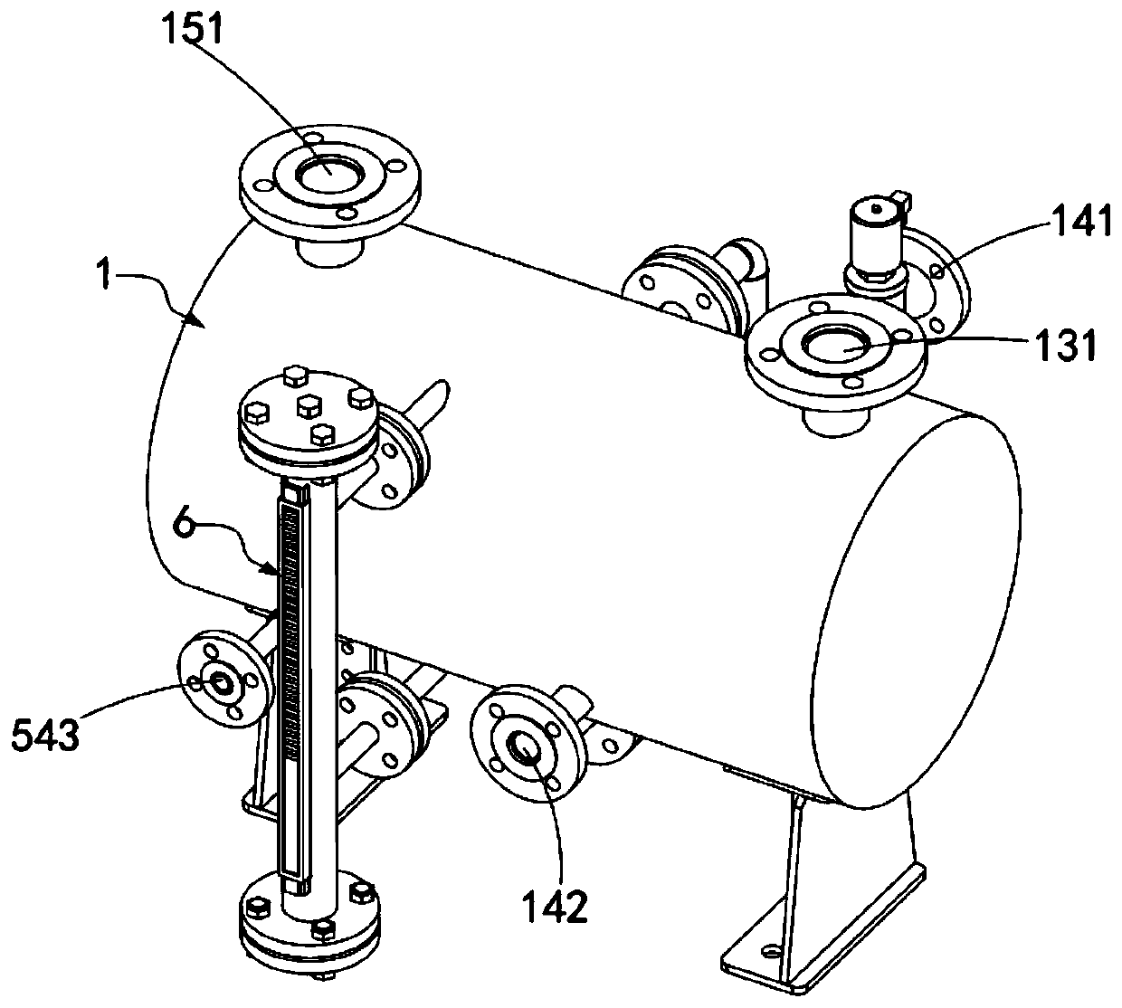
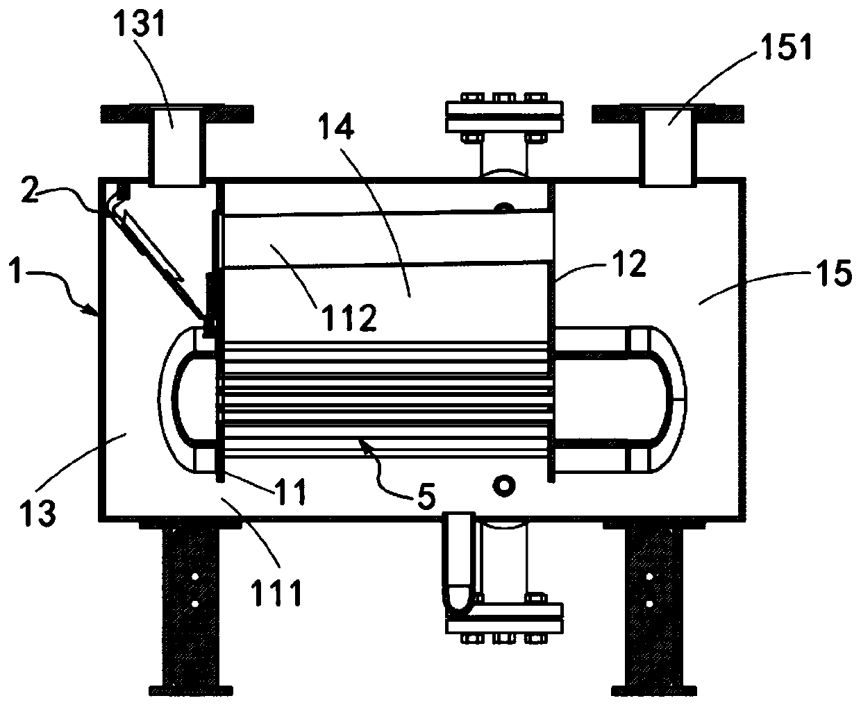
[0054] like Figure 1 to Figure 5 As shown, a gas-liquid separator includes a separation tank 1, in which the separation tank 1 is divided into first and second division plates 11 and 12 in the axial direction. chamber 13, the second chamber 14 and the third chamber 15, and the first chamber 13, the second chamber 14 and the third chamber 15 pass through the first partition plate 11 and the second partition The circulation port 111 provided at the bottom of the partition plate 12 communicates, and a communication pipe 112 connecting the first chamber 13 and the third chamber 15 is provided between the first partition board 11 and the second partition board 12 , the top of the first chamber 13 is provided with a gas-liquid inlet 131, and the top of the third chamber 15 is provided with an exhaust port 151 for exhausting exhaust gas;
[0055] It also includes a liquid stagnation device 2 arranged in the first chamber 13, and the liquid stagnation device 2 includes a guide plate...
Embodiment 2
[0070] Image 6 It is a structural schematic diagram of Embodiment 2 of a gas-liquid separator of the present invention; as Figure 7 As shown, the components that are the same as or corresponding to those in the first embodiment are marked with the corresponding reference numerals in the first embodiment. For the sake of simplicity, only the differences from the first embodiment will be described below. This embodiment two and figure 1 The difference of the shown embodiment one is:
[0071] like Image 6 and Figure 7 As shown, an overflow pipe 3 is provided in the second chamber 14, and the overflow pipe 3 includes a vertical pipe portion 31, a U-shaped pipe portion 32 and an L-shaped pipe portion 33, and the vertical pipe portion 31 The lower end is located below the working liquid level of the second chamber 14, the U-shaped pipe portion 32 is located between the vertical pipe portion 31 and the L-shaped pipe portion 33, and one end of the U-shaped pipe portion is conn...
Embodiment 3
[0084] Figure 8 It is a schematic structural view of Embodiment 3 of a gas-liquid separator of the present invention; as Figure 7 As shown, the components that are the same as or corresponding to those in the first embodiment are marked with the corresponding reference numerals in the first embodiment. For the sake of simplicity, only the differences from the first embodiment will be described below. This embodiment three and figure 1 The difference of the shown embodiment one is:
[0085] like Figure 8 and Figure 9 As shown, the upper part of the second chamber 14 is provided with a replenishment hole 141 communicating with the external liquid supply system, and a liquid return hole 142 is provided on the bottom side of the second chamber 14, and the liquid return hole 142 is connected to the pump outside the separation tank 1. body connected.
[0086] Further, a cooler 5 is arranged in the separation tank 1, and the cooler 5 is arranged across the first chamber 13, ...
PUM
 Abstract
Description
Claims
Application Information
 - R&D
- Intellectual Property
- Life Sciences
- Materials
- Tech Scout
- Unparalleled Data Quality
- Higher Quality Content
- 60% Fewer Hallucinations
Browse by: Latest US Patents, China's latest patents, Technical Efficacy Thesaurus, Application Domain, Technology Topic, Popular Technical Reports.
© 2025 PatSnap. All rights reserved.Legal|Privacy policy|Modern Slavery Act Transparency Statement|Sitemap|About US| Contact US: help@patsnap.com