
Precise oil filtering and impurity removing equipment for space shuttles

A space shuttle, sophisticated technology, applied in the direction of filtration separation, filtration loop, separation method, etc., can solve the problems of difficult separation of water, difficult to remove, inability to expand oil surface area, etc.

Inactive Publication Date: 2020-06-09
向曼婷
View PDF11 Cites 0 Cited by
  • Summary
  • Abstract
  • Description
  • Claims
  • Application Information

AI Technical Summary

Problems solved by technology

[0003] When the existing oil filtering equipment performs oil filtering work, the impurities in the lubricating oil are filtered first, and then the water is treated. When there is water in the oil, some impurities will be wrapped in the mixture of oil and water. In the air bubbles, it is difficult to be removed; in addition, the existing technology often adopts the method of evaporation and condensation for the removal of water in the oil. Although this method can remove part of the water, it cannot expand the surface area of ​​the oil, so that part of the water is evaporated. It is difficult to separate out during the process, so a precision oil filter and impurity removal equipment for aerospace aircraft came into being

Method used


Image

  • Precise oil filtering and impurity removing equipment for space shuttles
  • Precise oil filtering and impurity removing equipment for space shuttles
  • Precise oil filtering and impurity removing equipment for space shuttles

Examples


Embodiment Construction

[0022] The following will clearly and completely describe the technical solutions in the embodiments of the present invention with reference to the accompanying drawings in the embodiments of the present invention. Obviously, the described embodiments are only some, not all, embodiments of the present invention. Based on the embodiments of the present invention, all other embodiments obtained by persons of ordinary skill in the art without making creative efforts belong to the protection scope of the present invention.

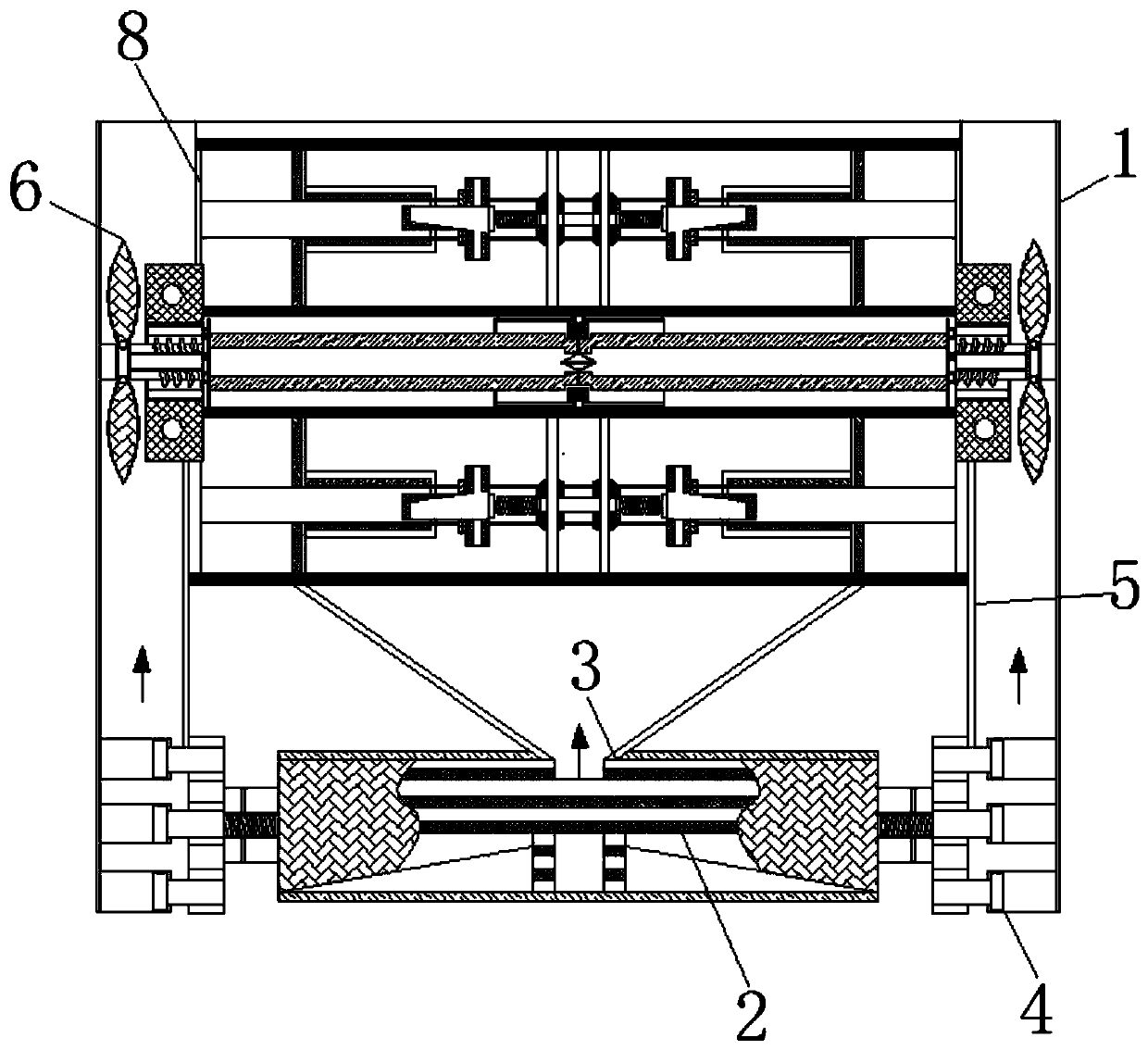
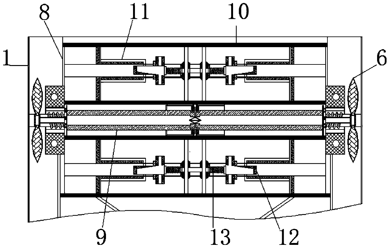
[0023] see Figure 1-6 , a precision oil filter and impurity removal device for aerospace aircraft, comprising a housing 1, the inner bottom wall of the housing 1 is fixedly connected with a vent pipe 2, the surface of the vent pipe 2 is provided with a heating tank 3, and the heating tank 3 and the filter box 8 are on the same vertical line, and the surface of the heating tank 3 is fixedly connected with a gas collecting plate, and the function of the gas col...


PUM


Abstract

The invention relates to the technical field of filtering of lubricating oil for aircrafts, and discloses precise oil filtering and impurity removing equipment for space shuttles. The precise oil filtering and impurity removing equipment comprises a shell, wherein the inner bottom wall of the shell is fixedly connected with a breather pipe; a heating groove is formed in the surface of the breatherpipe; stretching pipes are movably connected to the two sides of the breather pipe; the surfaces of the stretching pipes are fixedly connected with air supply pipes; fan impellers are arranged in andmovably connected with the air supply pipes; rotating shafts are arranged on and movably connected with the surfaces of the fan impellers; separated filtering boxes are movably connected to the surfaces of the rotating shafts; expansion grooves are formed in the separated filtering boxes; sliding rails are arranged in and fixedly connected to the separated filtering boxes and located on the two sides of the expansion grooves; and extension pipes are slidably connected to the surfaces of the sliding rails. Homogenizing springs shake to break mixed bubbles of oil and water, and meanwhile, steamflowing out of the heating groove is blown to the surfaces of the separated filtering boxes, so the water in the oil is evaporated and flows out of steam grooves; and therefore, the effect of conducting water surface area expanding treatment separation in step-by-step filtering is achieved.

Description

technical field [0001] The invention relates to the technical field of lubricating oil filtering for aircraft, in particular to precision oil filtering and impurity removal equipment for aerospace aircraft. Background technique [0002] Airplanes are the means of transportation for people to travel. Due to the particularity of the work of the aircraft, the lubricating oil used must be treated with precision oil filtering equipment before use, so as to avoid accidents caused by insufficient lubrication of aircraft parts; and precision oil filtering equipment The function is to purify and filter unqualified hydraulic oil and high-precision lubricating oil, and filter out impurities and water in the oil. [0003] When the existing oil filtering equipment performs oil filtering work, the impurities in the lubricating oil are filtered first, and then the water is treated. When there is water in the oil, some impurities will be wrapped in the mixture of oil and water. In the air ...

Claims


Application Information

Patent Timeline
IPC IPC(8): B01D36/00
CPCB01D36/00
Inventor 向曼婷莫云任梁文建
Owner 向曼婷
Learn More