
Macro-micro composite constant-pressure polishing device and method

A polishing device and polishing head technology, applied in the field of optical polishing, can solve the problems of large pressure control range, error, long polishing iteration time, etc., and achieve the effect of high polishing accuracy

Active Publication Date: 2020-06-05
广州精点科技有限公司
View PDF13 Cites 5 Cited by
  • Summary
  • Abstract
  • Description
  • Claims
  • Application Information

AI Technical Summary

Problems solved by technology

However, this method has a large pressure control range, which is prone to overshoot and makes the polishing pressure too high.
The Chinese invention patent with the publication number CN104772661A is a processing method for full-band high-precision aspheric optical elements. Iterative processing is used to gradually converge the polished surface shape, but the polishing iteration time is long
[0005] Due to the errors of various factors in the existing patented polishing technology, including polishing pressure, polishing speed, polishing residence time and the precision of the equipment, the convergence time of the polished surface shape error is long, and it needs to undergo multiple superimposed polishings to gradually converge.
Among them, constant pressure polishing is difficult to control within a small error range, resulting in excessive errors between the polishing removal model and theoretical calculations, which eventually lead to errors between the actual polishing effect and the theoretical polishing effect

Method used


Image

  • Macro-micro composite constant-pressure polishing device and method
  • Macro-micro composite constant-pressure polishing device and method
  • Macro-micro composite constant-pressure polishing device and method

Examples


Embodiment Construction

[0023] In order to make the object, technical solution and advantages of the present invention clearer, the present invention will be further described in detail below in conjunction with the accompanying drawings.

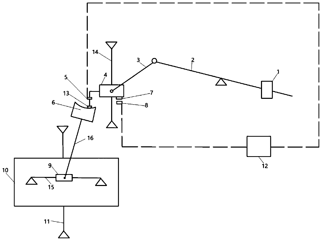
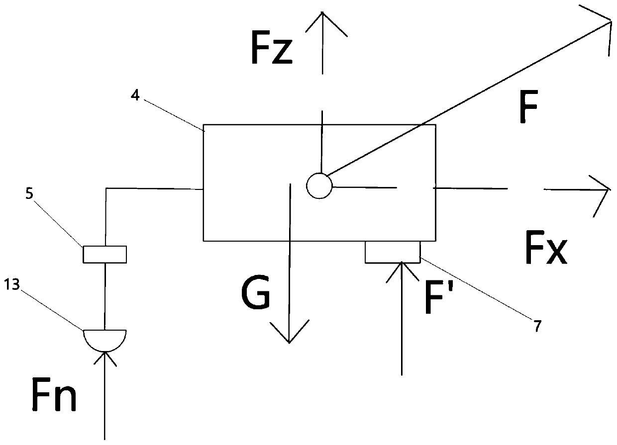
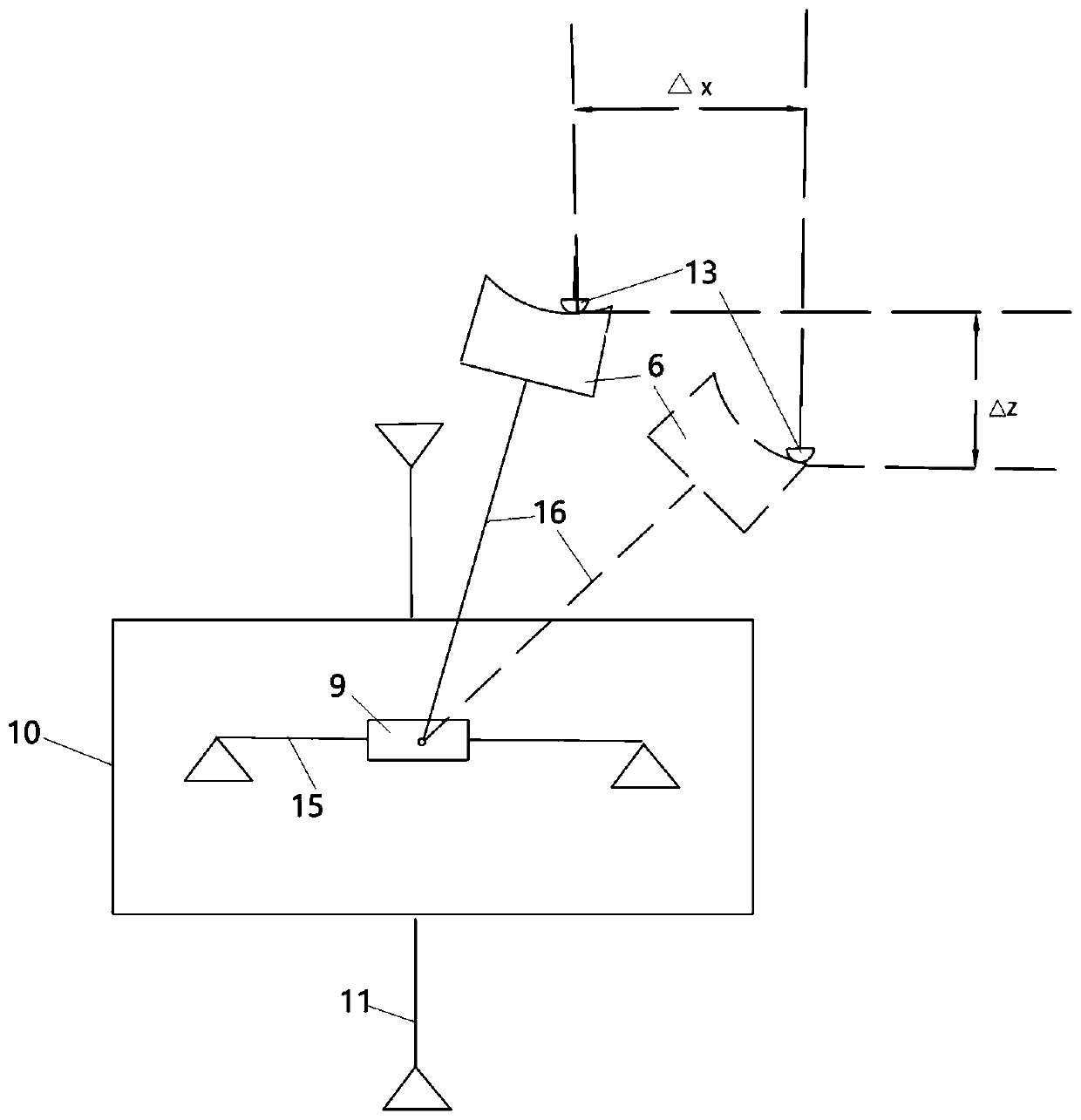
[0024] Such as figure 1 As shown, the present invention provides an implementation case of a macro-micro compound constant pressure polishing device and method, which includes an adjustment weight 1, a force applying lever 2, a force transmission lever 3, an air flotation guide block 4, a pressure sensor 5, a mold Kernel 6, permanent magnetic drop 7, magnetic device 8, left and right moving table 9, up and down lift table 10, up and down lead screw 11, pressure controller 12, polishing head 13, air bearing guide rail 14, left and right lead screw 15, rotating shaft 16.

[0025] figure 1 The schematic diagram is a schematic diagram of the movement of a mechanical structure of the present invention. It is a commonly used motion scheme expression method in engineer...


PUM


Abstract

The invention discloses a macro-micro composite constant-pressure polishing device and method. The method comprises the following steps of adjusting the polishing pressure by using a lever structure,counterweights at the two ends of a lever, and the force arm changes of the lever; when polishing equipment is used for polishing processing on the surface of a rotating symmetric non-spherical die core, the polishing position is controlled by using a left and right moving shaft and a rotating swinging shaft, the position of a die core polishing point is kept unchanged in space by utilizing a lifting servo shaft in space, and the polishing pressure is kept stable in the macro perspective by combining a lever principle. A polishing head is provided with a pressure sensor and an electromagneticforce device. The electromagnetic force device is controlled by polishing pressure changes to adjust and compensate for polishing pressure changes in the micro perspective. Constant pressure is ensured in the polishing process through closed-loop control. By means of the macro-micro composite constant-pressure polishing device and the method, the stability of polishing pressure is kept through a macro-micro composite method, and the control precision is higher.

Description

technical field [0001] The invention relates to the technical field of optical polishing, in particular to a macro-micro composite constant pressure polishing device and method. Background technique [0002] With the development of optoelectronic technology, more and more aspherical lenses are used in optical systems to improve the disadvantages of large aberration, small field of view and large volume of optical systems in traditional spherical lens optical systems. There are two commonly used aspheric lens manufacturing techniques, cold processing and hot pressing. Cold processing technology includes grinding and polishing of lens blanks. This technology has low production efficiency and is often used in the manufacture of large-diameter optical lenses in the fields of astronomy and military industry. Hot press forming technology uses high-precision molds to heat the lens blank and apply a certain pressure when the glass lens is in a high elastic state. After a certain pe...

Claims


Application Information

Patent Timeline
Patent Type & Authority Applications(China)
IPC IPC(8): B24B13/00B24B49/16B24B41/00
CPCB24B13/00B24B41/007B24B49/165
Inventor 朱相优张嘉荣邓建南卓少木
Owner 广州精点科技有限公司
Learn More