
A mold for easy collection

A mold and scrap technology, applied in the field of molds that are easy to collect materials, can solve the problems of increasing the work intensity of the staff and cumbersome operations

Active Publication Date: 2021-03-02
武汉市尚佳盛汽车配件有限公司
View PDF8 Cites 0 Cited by
  • Summary
  • Abstract
  • Description
  • Claims
  • Application Information

AI Technical Summary

Problems solved by technology

[0004] The prior art solution above has the following defects: the outer wall of the bottom end of the first chute is in contact with the vibrating device, and the electronic vibrator is set at the midline position of the first chute, and the electronic vibrator is opposite to the first chute at the abutting position. During the long-term collision and vibration of the bottom wall of the chute, the wear degree of the bottom wall of the first chute gradually increases. When replacing the first chute, the vibration device or the mold must be disassembled before the first chute can be disassembled. The operation is cumbersome and increases Work intensity of large staff

Method used


Image

  • A mold for easy collection
  • A mold for easy collection
  • A mold for easy collection

Examples


Embodiment Construction

[0033] The present invention will be described in further detail below in conjunction with the accompanying drawings.

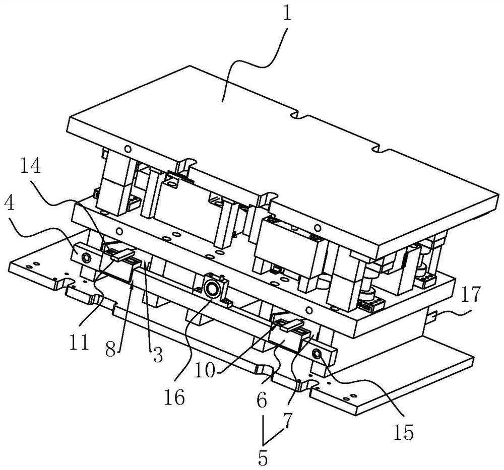
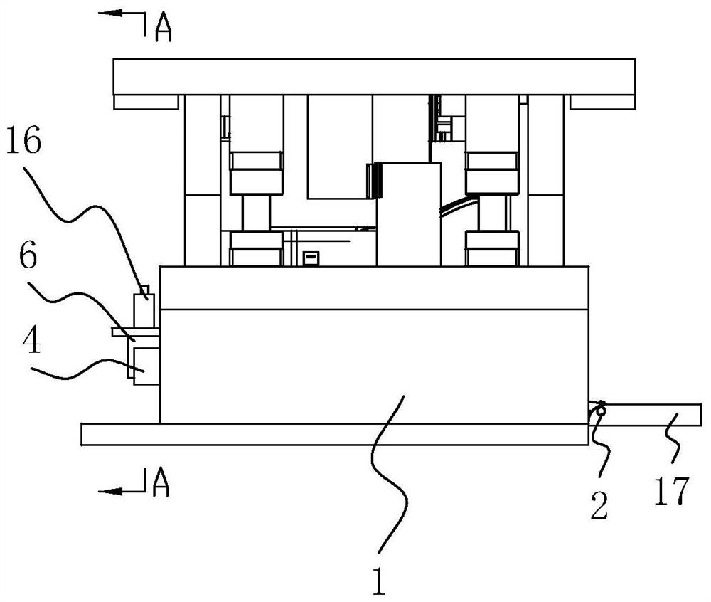
[0034] refer to figure 1 , is a mold that is convenient for receiving materials disclosed by the present invention, including a body 1, the body 1 is provided with a waste material port and a waste material groove 3 for collecting waste materials, the waste material port is used for waste materials to fall (not shown in the figure), and the waste materials Groove 3 is used to collect waste. When the mold is processing the plate, the plate located at the waste port is punched into a hole, and the waste falls from the waste port into the waste groove 3. In order to facilitate the collection of waste, the body 1 is placed in the waste port. There is a recovery section below, the recovery section includes a pole 4 fixedly connected to the body 1 and a waste plate 5 detachable from the pole 4, the waste plate 5 is inclined, and the pole 4 is one end of the opening...


PUM


Abstract

The invention relates to a mold for easy material collection, which includes a body, the body is provided with a waste material port and a waste material groove, the body is provided with a recovery part, and the recovery part includes a support rod and a waste material plate, and the support rod is located at One end of the waste trough is fixedly connected with a vibration assembly to the pole; the waste plate includes a concave plate and a blanking plate, and the height of the blanking plate decreases gradually along the direction away from the concave plate; The concave plate is provided with a concave groove, the inner wall of the concave groove is fixedly connected with a clamping rod, the pole is provided with a clamping groove, and one end of the clamping rod passing through the clamping groove is provided with a limiting member. Through the above technical proposal, the present invention ensures that the waste material falls from the waste material plate, facilitates the installation and disassembly of the waste material plate, and improves the working efficiency of the die stamping plate.

Description

technical field [0001] The invention relates to the technical field of stamping equipment, in particular to a mold that is convenient for receiving materials. Background technique [0002] At present, the strut of the engine is formed by stamping between the upper mold and the lower mold. The strut of the engine needs to be punched. In the field production, the lower mold is generally equipped with a waste collection device, which is placed on the base of the mold. The bottom of the seat collects the stamping overflow waste falling from the mold surface or the waste generated by product trimming, etc. The purpose is to ensure that the mold production does not stop and the operation of the entire production line is guaranteed. [0003] The existing patent notification number is the Chinese patent of CN108723233A, which proposes a mold waste collection device, the mold waste collection device is composed of a waste chute and a waste hopper for exporting waste, and the waste ch...

Claims


Application Information

Patent Timeline
Patent Type & Authority Patents(China)
IPC IPC(8): B21D28/34B21D37/12B21D45/00
CPCB21D28/34B21D37/12B21D45/00
Inventor 李军何丽平刘洪新文佳思樊世杰刘水荣
Owner 武汉市尚佳盛汽车配件有限公司
Learn More