
A filter, duplexer, high-frequency front-end circuit and communication device

A filter and frequency technology, which is applied in the fields of filters, duplexers, high-frequency front-end circuits and communication devices, can solve the problems of narrowing filter bandwidth, deteriorating RF front-end transceiver performance, and increasing RF link loss, etc. Achieve the effect of improving the roll-off characteristics, improving the temperature drift characteristics, and realizing the insertion loss

Active Publication Date: 2021-08-10
ROFS MICROSYST TIANJIN CO LTD
View PDF10 Cites 0 Cited by
  • Summary
  • Abstract
  • Description
  • Claims
  • Application Information

AI Technical Summary

Problems solved by technology

[0006] However, after the above-mentioned temperature compensation layer is introduced into the resonator, the performance of the resonator deteriorates, which is mainly reflected in the increase of resonator loss and the electromechanical coupling coefficient (Kt 2 ) becomes smaller
The loss of the resonator directly affects the passband insertion loss characteristics of the filter, thereby increasing the loss in the RF link and deteriorating the transceiver performance of the RF front-end
The electromechanical coupling coefficient becomes smaller, and the frequency difference between the series resonant frequency and the parallel resonant frequency of the resonator decreases under certain frequency conditions, and the roll-off characteristics of the filter may be improved, but at the same time the bandwidth of the filter will also be narrowed. In most communication systems, the bandwidth of the filter is proposed according to the system requirements, and the bandwidth cannot be narrowed without limit

Method used


Image

  • A filter, duplexer, high-frequency front-end circuit and communication device
  • A filter, duplexer, high-frequency front-end circuit and communication device
  • A filter, duplexer, high-frequency front-end circuit and communication device

Examples


Embodiment Construction

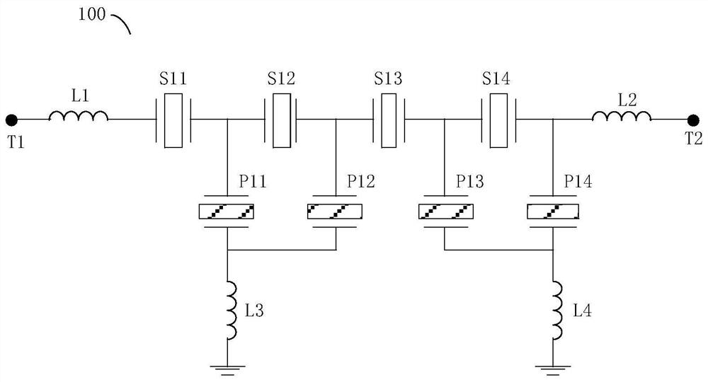
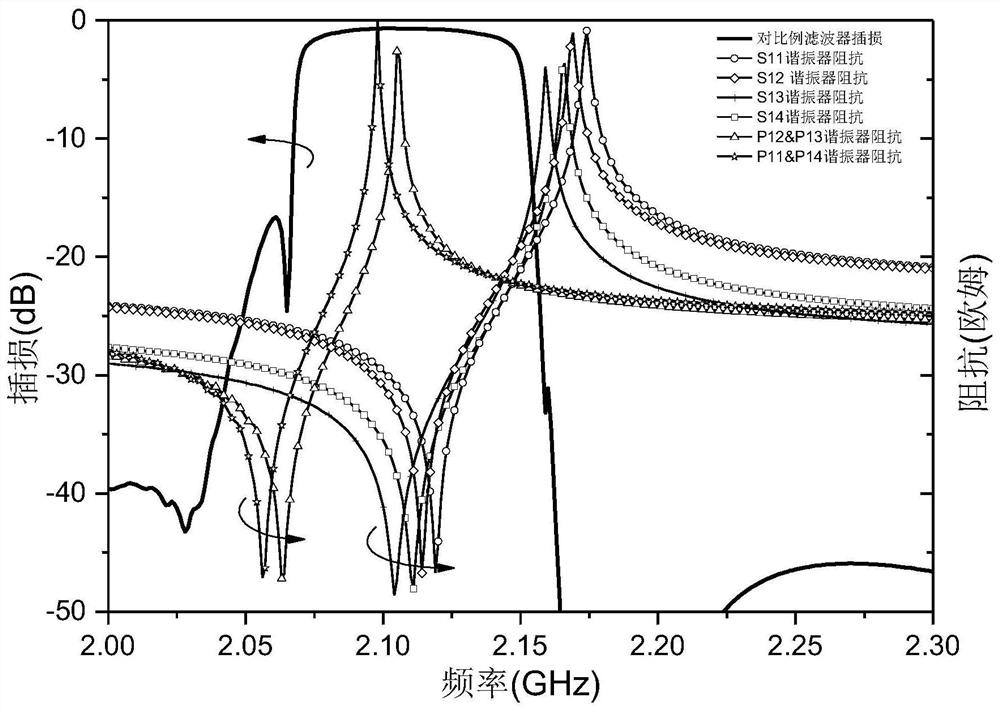
[0054] figure 1 It is a circuit diagram of a filter in the prior art, wherein T1 is the input terminal of the filter 100, T2 is the output terminal of the filter, and the input terminal T1 and the output terminal T2 are ports connected to the external signal of the filter. Between the input terminal T1 and the output terminal T2, a series of series first resonators S11, S12, S13 and S14 are connected in series with each other at series path positions. Between the input terminal T1 and the series resonator S11, a series inductor L1 is connected in series; between the input terminal T2 and the series resonator S14, a series inductor L2 is connected in series. One end of the parallel resonator P11 is connected to a node between the series resonators S11 and S12, one end of the parallel resonator P12 is connected to a node between the series resonators S12 and S13, and the other ends of the parallel resonators P11 and P12 are connected to each other and One end of the parallel in...


PUM


Abstract

The present invention relates to the technical field of filters, in particular to a filter, a duplexer, a high-frequency front-end circuit and a communication device. The filter includes a plurality of series resonators and a plurality of parallel resonators, part of the series resonators and / or Or part of the parallel resonator is a temperature-compensated resonator, and the temperature-compensated resonator includes a temperature compensation layer. Compared with the existing ordinary filter or the filter whose resonators are all temperature-compensated resonators, the technical solution provided by the present invention can realize the high roll-off requirement and good performance of the filter without affecting the filter bandwidth. Temperature characteristics; at the same time, since the loss of temperature-compensated resonators is greater than that of ordinary resonators, the more temperature-compensated resonators are introduced into the filter, the worse the insertion loss of the filter will be. The temperature-compensated resonator is designed to minimize the deterioration of the filter insertion loss while improving the temperature drift characteristics of the filter.

Description

technical field [0001] The invention relates to the technical field of filters, in particular to a filter, a duplexer, a high-frequency front-end circuit and a communication device. Background technique [0002] With the development of wireless communication applications, people have higher and higher requirements on the data transmission rate. Corresponding to the data transmission rate is the high utilization rate of spectrum resources and the complexity of spectrum. The complexity of the communication protocol puts forward strict requirements on the various performances of the radio frequency system. In the radio frequency front-end module, the radio frequency filter plays a vital role. It can filter out out-of-band interference and noise to meet the requirements of the radio frequency system and The requirements of the communication protocol for the signal-to-noise ratio. [0003] RF filters are mainly used in wireless communication systems, for example, RF front-ends o...

Claims


Application Information

Patent Timeline
Patent Type & Authority Patents(China)
IPC IPC(8): H03H9/70H03H9/54
CPCH03H9/54H03H9/706
Inventor 庞慰边子鹏
Owner ROFS MICROSYST TIANJIN CO LTD
Learn More