Working method of knob device

A working method and knob technology, applied in the input/output process of data processing, instruments, electrical digital data processing, etc., can solve the coordinate jitter of conductive contact position, misjudgment of rotation angle or position, and poor smoothness of application operation. and other problems to achieve the effect of improving the smoothness of operation

Pending Publication Date: 2020-06-02
CHUNGHWA PICTURE TUBES LTD
View PDF8 Cites 1 Cited by
  • Summary
  • Abstract
  • Description
  • Claims
  • Application Information

AI Technical Summary

Problems solved by technology

[0003] However, because the bottom of the conductive contact has a certain area, the capacitance change area of ​​the touch panel will cause irregular jitter in the determined position coordinates of the conductive contact during the capacitance dissipation process.
Therefore, when the knob is operated, the system misjudges the rotation angle or position, and then judges that the knob is repeatedly rotated clockwise and counterclockwise, resulting in poor operation fluency of the application program.

Method used


Image

  • Working method of knob device
  • Working method of knob device
  • Working method of knob device

Examples


Embodiment Construction

[0022] A number of implementations of the present invention will be disclosed below with the accompanying drawings. For the sake of clarity, many practical details will be described together in the following description. It should be understood, however, that these practical details should not be used to limit the invention. That is, in some embodiments of the present invention, these practical details are unnecessary. In addition, for the sake of simplifying the drawings, some well-known and commonly used structures and elements will be shown in a simple and schematic manner in the drawings. Also, the thicknesses of layers and regions in the drawings may be exaggerated for clarity, and the same reference numerals denote the same elements in the description of the drawings.

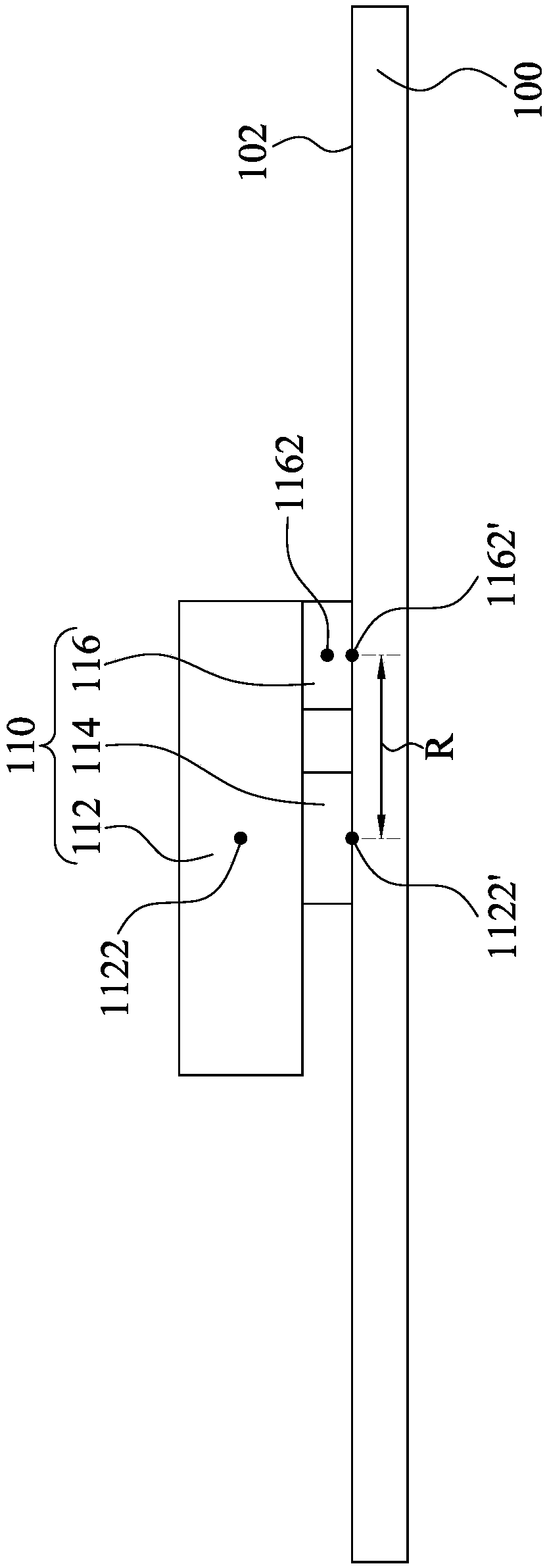
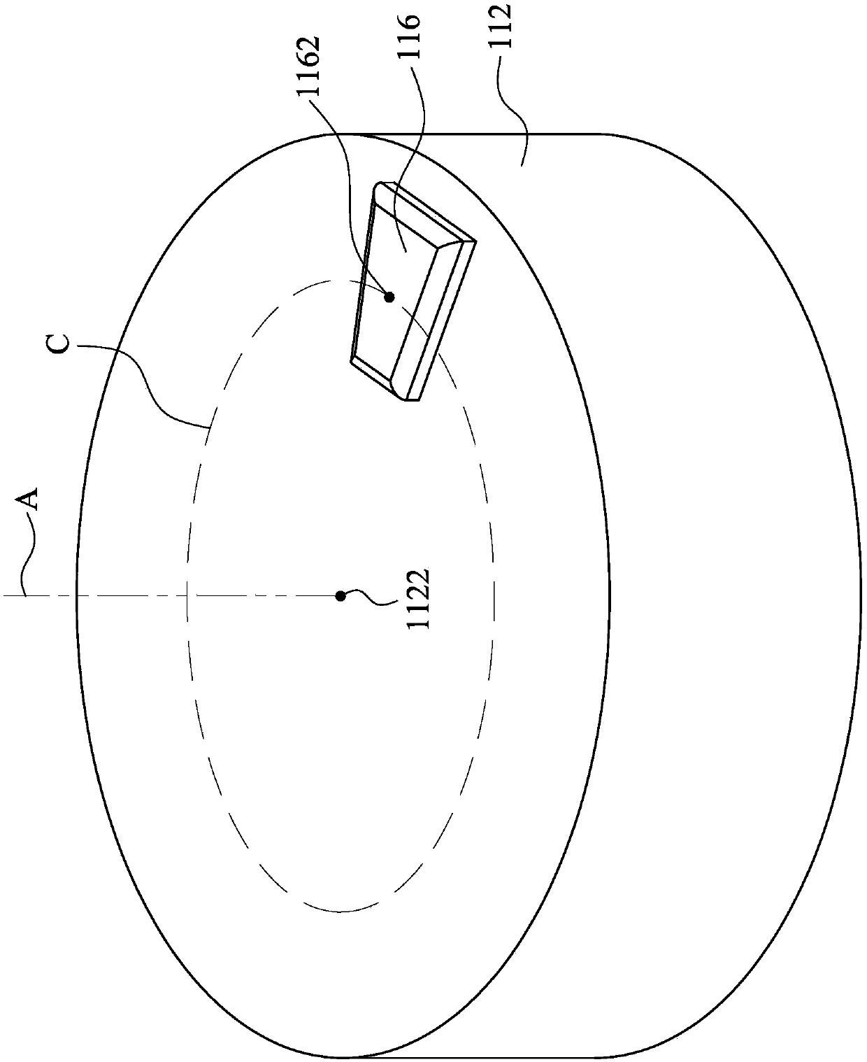
[0023] figure 1 It is a side view of the touch panel 100 with the knob device 110 according to an embodiment of the present invention. figure 2 for figure 1 The perspective view of the knob 112 and t...


PUM


Abstract

The invention discloses a working method of a knob device, which comprises the following steps: judging a first position of a conductive contact of a knob, the first position being located on one of aplurality of touch point areas on the surface of a touch panel, the touch point areas being separated from each other and arranged along an arc; after the knob rotates by an angle, judging a second position of the conductive contact of the knob, wherein the second position is located on one of the touch point areas; and when the first position and the second position are respectively positioned on two of the touch point areas, enabling the touch panel to judge whether the knob rotates clockwise or anticlockwise according to the two touch point areas. According to the working method of the knob device, the knob can be prevented from being misjudged to be in the shaking state of repeated clockwise rotation and anticlockwise rotation, and the operation fluency of an application program of the touch panel is improved.

Description

technical field [0001] The present invention relates to a working method of a knob device, in particular to a working method of a knob device used for a touch panel. Background technique [0002] When the traditional knob device is applied to the touch panel, the contact coordinates of the conductive contacts are determined according to the capacitance change generated on the touch panel. Then it is known whether the knob rotates clockwise or counterclockwise through the position and angle change of the conductive contact. [0003] However, because the bottom of the conductive contact has a certain area, the capacitance change area of ​​the touch panel will cause irregular jitter in the determined position coordinates of the conductive contact during the capacitance dissipation process. Therefore, when the knob is operated, the system misjudges the rotation angle or position, and then judges that the knob is repeatedly rotated clockwise and counterclockwise, resulting in po...

Claims


Application Information

Patent Timeline
Patent Type & Authority Applications(China)
IPC IPC(8): G06F3/041G06F3/044
CPCG06F3/044G06F3/0416
Inventor 张维甫李青龙陈鸿祥
Owner CHUNGHWA PICTURE TUBES LTD
Why Eureka
Try Eureka