Cooling Fan

A technology of cooling fan and fan frame, which is applied to the components of pumping device for elastic fluid, non-variable-capacity pump, pump device, etc. Fan operation quality and other issues

Active Publication Date: 2016-07-20
SUNONWEALTH ELECTRIC MACHINE IND
View PDF6 Cites 1 Cited by
  • Summary
  • Abstract
  • Description
  • Claims
  • Application Information

AI Technical Summary

Problems solved by technology

[0004] However, please refer to figure 2 As shown, since the metal base 91 has a magnetic conduction effect, the magnetic force lines M generated by the permanent magnet 932 can pass through the metal base 91 on both sides of the magnetic attraction range D2, so that the magnetic force lines M generated by the permanent magnet 932 are relatively Therefore, the axial magnetic attraction between the permanent magnet 932 and the metal base 91 is too large, and the excessive axial magnetic attraction is easy to increase the resistance when the fan wheel 93 rotates, thereby affecting the cooling fan. running quality

Method used


Image

  • Cooling Fan
  • Cooling Fan
  • Cooling Fan

Examples


Embodiment Construction

[0037] In order to make the above and other objects, features and advantages of the present invention more comprehensible, the following specifically cites the embodiments of the present invention together with the accompanying drawings and describes them in detail as follows.

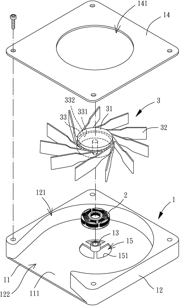
[0038] Please refer to image 3 and Figure 4 As shown, the cooling fan of the present invention may include a fan frame 1 , a stator 2 and a fan wheel 3 . The inside of the fan frame 1 can accommodate the stator 2 and the fan wheel 3 , and the stator 2 is used to drive the fan wheel 3 to rotate.

[0039] The fan frame 1 has a metal base 11 made of magnetically permeable material. The metal base 11 is provided with a side wall 12 and a shaft joint 13. The side wall 12 is provided with an air inlet 121 and an air outlet. 122; wherein the fan frame 1 can be a hollow frame structure of various shapes that can accommodate and combine the above-mentioned stator 2 and the above-mentioned fan wheel 3, and t...


PUM


Abstract

A cooling fan comprises a fan frame, a stator and a fan wheel. The fan frame is provided with a metal base. The metal base is provided with a shaft connecting part. The stator is combined with the fan frame. The fan wheel comprises a hub, multiple blades and a permanent magnet. The hub is rotationally combined with the shaft connecting part of the fan frame. The blades are combined with the peripheral wall of the outer side of the hub. The permanent magnet is arranged on the peripheral wall of the inner side of the hub. A radial rotation range is reserved between the hub and the metal base. A magnetic attraction range is reserved between the permanent magnet and the metal base. A hollowed-out part is arranged on the metal base within the radial rotation range. The hollow-out part is located outside the magnetic attraction range. By the adoption of the hollowed-out part, magnetic lines generated by the permanent magnet can be dispersed, and therefore resistance generated when the fan wheel rotates can be reduced.

Description

technical field [0001] The invention relates to a heat dissipation fan, in particular to a heat dissipation fan which can rotate stably by means of magnetic attraction. Background technique [0002] Please refer to figure 1 As shown, the conventional cooling fan 9 roughly includes a metal base 91 , a stator 92 and a fan wheel 93 . There is a shaft tube 911 in the center of the metal base 91; the stator 92 is combined with the outer peripheral wall of the shaft tube 911; the fan wheel 93 includes a hub 931 and a permanent magnet 932, and the hub 931 is rotatably combined by a rotating shaft 933 In the shaft tube 911, the permanent magnet 932 is arranged on the inner peripheral wall of the hub 931, and there is an air gap between the permanent magnet 932 and the stator 92; thereby, when the cooling fan 9 is activated, current can be input to The stator 92 enables the stator 92 to drive the fan wheel 93 to rotate through the air gap. The detailed structural composition and o...

Claims


Application Information

Patent Timeline
Patent Type & Authority Applications(China)
IPC IPC(8): F04D25/08F04D29/52
Inventor 洪银树
Owner SUNONWEALTH ELECTRIC MACHINE IND
Why Eureka
Try Eureka