
Gradient detection system based on pulse pumping magnetometer

A technology of gradient detection and detection system, which is applied in magnetic gradient measurement, magnetic field measurement using the principle of magnetic flux control, and the size/direction of the magnetic field. Limiting the application of gradient magnetometer and other issues to achieve the effect of reducing system complexity, wide application scenarios, and high signal-to-noise ratio

Inactive Publication Date: 2020-06-02
杭州量磁科技有限公司 +1
View PDF9 Cites 6 Cited by
  • Summary
  • Abstract
  • Description
  • Claims
  • Application Information

AI Technical Summary

Problems solved by technology

[0004] The traditional gradient detection method is to use the signal subtraction of two different magnetometers to obtain a differential signal. Since the signal amplitude and noise level of the two magnetometers are different, the error obtained by direct subtraction is relatively large, and the volume is large and the cost is high.
[0005] Traditional gradient magnetometers use optical pump magnetometers or fluxgate magnetometers to obtain gradient signals, but since most output signals of other types of magnetometers such as optical pump magnetometers or fluxgate magnetometers are relative voltage signals, calibration is required , cannot maintain absolute consistency
In addition, there are radio frequency coils in the traditional gradient magnetometer and the radio frequency coil cannot be shared. In order to avoid crosstalk between adjacent magnetometers, a certain distance needs to be separated, and the distance between the gradient magnetometers cannot be set arbitrarily, which limits the application of the gradient magnetometer.

Method used


Image

  • Gradient detection system based on pulse pumping magnetometer
  • Gradient detection system based on pulse pumping magnetometer
  • Gradient detection system based on pulse pumping magnetometer

Examples


Embodiment Construction

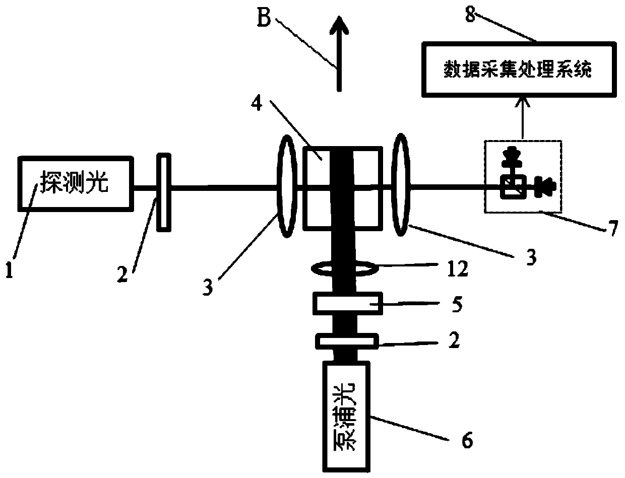
[0017] The present invention will be further described below in conjunction with specific embodiments, and the advantages and characteristics of the present invention will become clearer along with the description. However, these embodiments are only exemplary and do not constitute any limitation to the scope of the present invention. Those skilled in the art should understand that the details and forms of the technical solutions of the present invention can be modified or replaced without departing from the spirit and scope of the present invention, but these modifications and replacements all fall within the protection scope of the present invention.

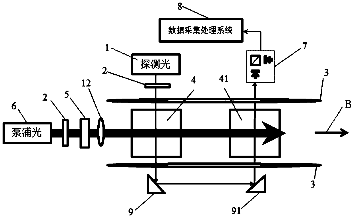
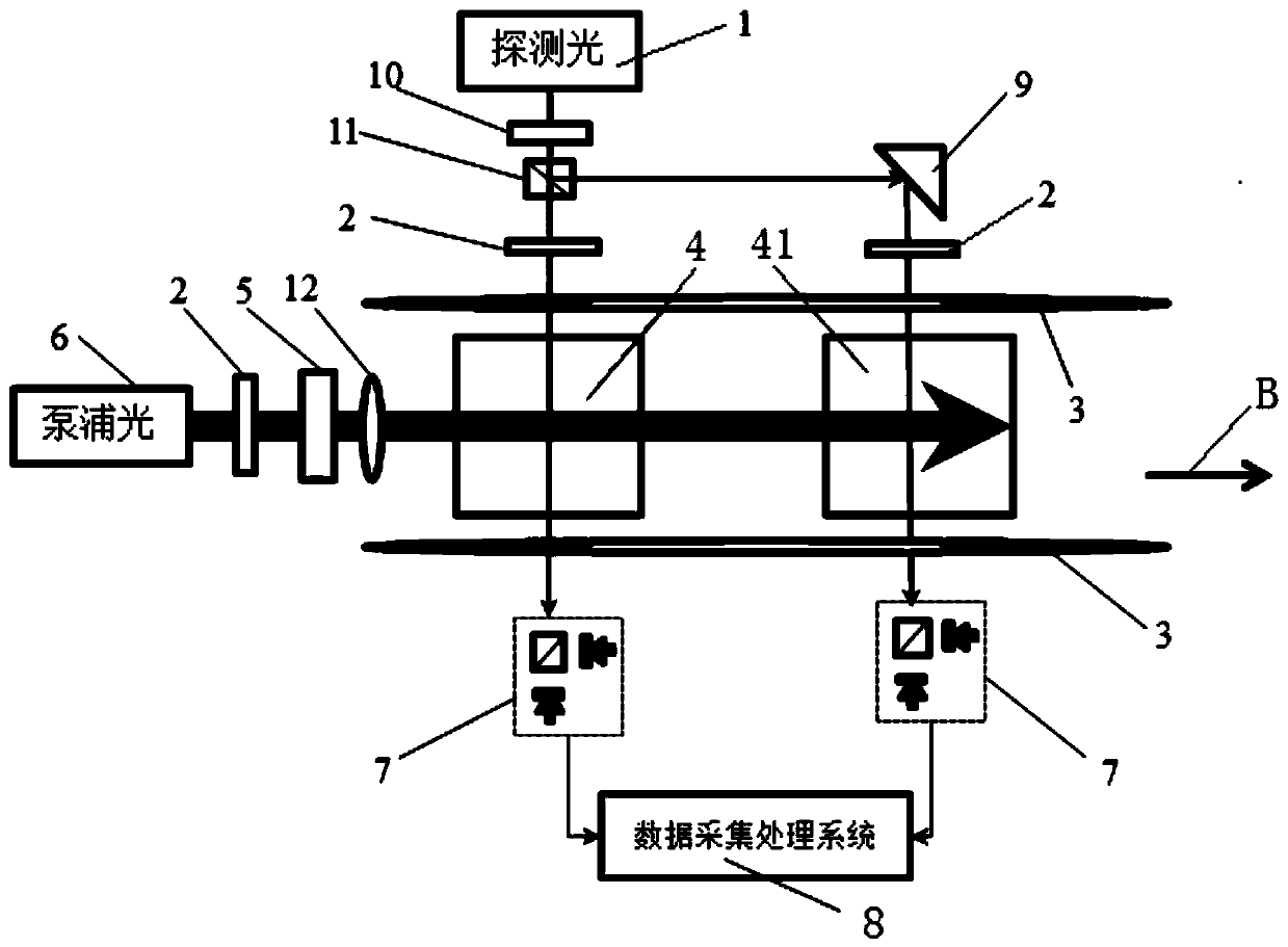
[0018] see figure 2 The illustrated embodiment comprises a first atomic gas chamber 4 and a second atomic gas chamber 41, and one end of the first atomic gas chamber 4 is provided with a pumping laser 6, a polarizer 2, a quarter glass 5 And a beam expander 12; a radio frequency coil 3 is provided at both ends of the probe li...


PUM


Abstract

The invention discloses a gradient detection system based on a pulse pumping magnetometer. The gradient detection system comprises a detection light laser, a polarizer, a radio frequency coil, a pulsetype pump light laser, a first atomic gas chamber, a second atomic gas chamber, a quarter-wave plate, detection light, a first reflector, a second reflector, a polarization detection system, a data acquisition system and the like. By setting the circular polarization gradient detection system of pump light or action modes of the pump light and probe light in the first atomic air chamber and the second atomic air chamber, magnetic field gradient values in the two air chambers are obtained. The gradient detection system combines two pulse pumping magnetometers together to share the pump light or the detection light, and subtracts the signals at the signal end or in the atomic gas chambers to extract the magnetic field gradient information, so that the consistency of the two magnetometers iseffectively improved, suppresses a signal-to-noise ratio, obtains a relatively accurate gradient value, reduces the size of the system, and saves the cost.

Description

technical field [0001] The invention relates to the technical field of pulse-pumped magnetometers, in particular to a gradient detection system based on pulse-pumped magnetometers. Background technique [0002] Magnetometers are used to detect weak magnetic field signals and are widely used in medicine, biology, geological exploration, material testing and other fields. In recent years, atomic magnetometers that use alkali metal atoms (such as potassium atoms, rubidium atoms, cesium atoms, etc.) Laser, atomic gas chamber, radio frequency coil and photodetector make up the system. The pulse-pumped magnetometer uses the optical pumping method to polarize the atoms to generate a macroscopic magnetic moment. Since the atoms in the magnetic field precess around the magnetic moment, the detection light detects the projection of the magnetic moment rotation, and the frequency of the rotation is proportional to The size of the external magnetic field can be obtained by analyzing t...

Claims


Application Information

Patent Timeline
IPC IPC(8): G01R33/022
CPCG01R33/022
Inventor 黄宇翔谷保磊陈齐霖
Owner 杭州量磁科技有限公司
Learn More