
Machining equipment for prefabricated box girder web steel bar frame

A technology for processing equipment and steel frames, which is applied in the field of processing equipment for prefabricated box girder belly steel frames, can solve the problems of high labor intensity, large labor input, and slow construction progress, etc., and achieve a simple and novel overall structure, ensuring operation safety, The effect of ensuring safety

Pending Publication Date: 2020-06-02
NO 4 ENG COMPANY LTD OF CCCC FIRST HARBOR ENG COMPANY
View PDF0 Cites 2 Cited by
  • Summary
  • Abstract
  • Description
  • Claims
  • Application Information

AI Technical Summary

Problems solved by technology

[0003] The prefabricated box girder web reinforcement frame includes vertically placed longitudinal reinforcement and horizontally placed transverse reinforcement frame. Currently, in prefabricated box girder construction, the bottom web reinforcement material of the box girder is basically artificially distributed, and the construction efficiency is low, and the labor input is relatively large. Many, the construction is inconvenient, the labor intensity of the workers is high, and the construction progress is slow, thus increasing the construction cost
In addition, the longitudinal reinforcement is fixedly connected to the horizontal reinforcement frame, but the current longitudinal reinforcement is generally placed after manual straightening, and there is no special equipment for stretching the ends of the longitudinal reinforcement, which will cause the longitudinal reinforcement of the box girder belly Rebar is not straight

Method used


Image

  • Machining equipment for prefabricated box girder web steel bar frame
  • Machining equipment for prefabricated box girder web steel bar frame
  • Machining equipment for prefabricated box girder web steel bar frame

Examples


Embodiment 1

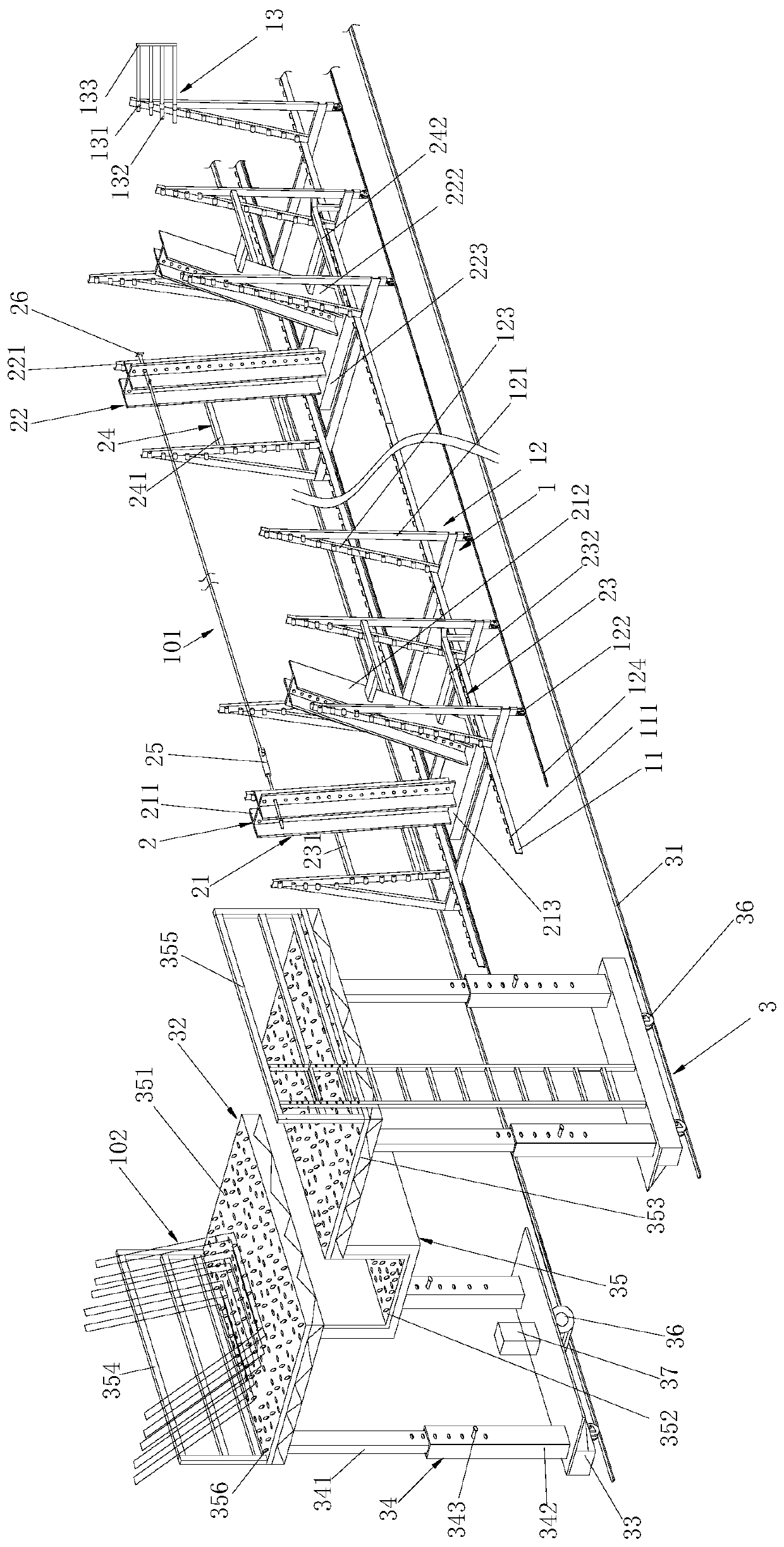
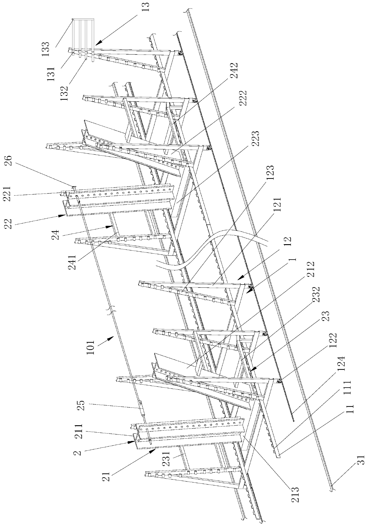
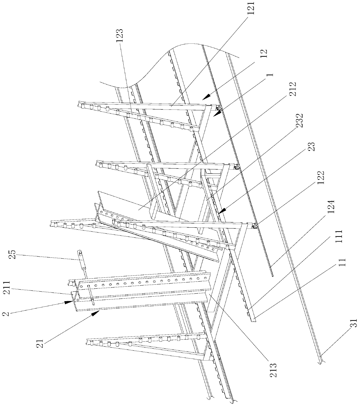
[0043] combine Figure 1 to Figure 7, processing equipment for prefabricated box girder abdominal reinforcement frame, said prefabricated box girder abdominal reinforcement frame includes longitudinal reinforcement 101 and transverse reinforcement frame 102, processing and installation equipment includes external positioning device 1, stretching device 2 and distribution device 3.

[0044] The outer positioning device 1 includes a first longitudinal positioning plate 11 for connecting the transverse reinforcement frame 102 and a plurality of longitudinally arranged first transverse positioning frames 12, and the two first longitudinal positioning plates 11 are arranged parallel to each other on a plurality of first transverse positioning frames. Inside the positioning frame 12 , the first transverse positioning frame 12 is connected with a plurality of first steel bar position adjustment assemblies 13 for positioning the longitudinal steel bars 101 .

[0045] The stretching de...

Embodiment 2

[0069] During the use of the above-mentioned processing equipment for prefabricating the abdominal reinforcement frame of a box girder, the longitudinal reinforcement 101 is installed first, and then the transverse reinforcement frame 102 is installed.

[0070] Before installing the longitudinal reinforcing bars 101 , the spacing distance of the longitudinal reinforcing bars 101 is firstly determined, and the spacing distance at this time is realized by the adjustment of the first reinforcing bar position adjustment assembly 13 . There are multiple sets of first steel bar position adjustment assemblies 13, and multiple sets of first steel bar position adjustment assemblies 13 are connected to the side walls of the first transverse oblique struts 123; the first steel bar position adjustment assemblies 13 include four first adjustment sleeves 131 Each first adjustment sleeve 131 is connected with a first adjustment horizontal sleeve rod 132 , and the ends of the four first adjust...

Embodiment 3

[0073] The cross-section of the transverse reinforcement frame 102 in the present invention is a trapezoidal frame shape, and the transverse reinforcement frame 102 can be adapted to be connected between a plurality of positioned longitudinal reinforcement bars 101. When the transverse reinforcement frame 102 is installed, the multiple transverse reinforcement bars The frame 102 is placed on the left discharge part 351 and the right discharge part 353 of the distribution vehicle, and the discharge worker stands on the middle stand part 352 and places the transverse reinforcement frame 102 between the two first longitudinal positioning plates 11 .

[0074] An installer working between the outer positioning devices 1 installs the transverse reinforcement frame 102 into the first positioning plate notch 111 of the first longitudinal positioning plate 11 . After the horizontal reinforcing bar frame 102 is installed, the worker welds the longitudinal reinforcing bar 101 and the tran...


PUM


Abstract

The invention discloses machining equipment for a prefabricated box girder web steel bar frame. The equipment comprises an outer positioning device, a stretching device and a distributing device, wherein the outer positioning device comprises a first longitudinal positioning plate for connecting transverse steel bar frames and a plurality of first transverse positioning frames, the two first longitudinal positioning plates are arranged in the plurality of first transverse positioning frames in parallel, and the first transverse positioning frames are connected with first steel bar position adjusting assemblies; the stretching device comprises a first stretching support seat and a second stretching support seat, which are connected with the first transverse positioning frames; the first stretching support seat is connected with one ends of longitudinal steel bars by first steel bar straightening assemblies, and the second stretching support seat is connected with the other ends of the longitudinal steel bars by second steel bar positioning assemblies; the distributing device comprises two first rails arranged on two sides of the outer positioning device and a distributing trolley connected to the first rails. The equipment has the advantages of being high in machining and installation efficiency for the box girder steel bar frame, novel in structure and high in safety, and facilitating machining.

Description

technical field [0001] The invention relates to the field of engineering machinery, in particular to processing equipment for prefabricating the abdominal reinforcement frame of a box girder. Background technique [0002] The box girder is a kind of beam in bridge engineering. The inside of the box girder is hollow, and there are flanges on both sides of the upper part, which is similar to a box, hence the name. The box girder of reinforced concrete structure is divided into prefabricated box girder and cast-in-place box girder. The prefabricated box girder combined with the bridge erecting machine can be erected after the completion of the substructure, which can speed up the progress of the project and save the construction period; the cast-in-place box girder is mostly used for large continuous bridges. Commonly divided by materials, there are two main types, one is prestressed reinforced concrete box girder, and the other is steel box girder. Among them, the prestresse...

Claims


Application Information

Patent Timeline
IPC IPC(8): B28B23/04B28B23/02B21F1/02
CPCB21F1/02B28B23/024B28B23/04
Inventor 杨龙龙刘光正常新乾张彪
Owner NO 4 ENG COMPANY LTD OF CCCC FIRST HARBOR ENG COMPANY
Learn More