
Automatic generation method of wavelength division emergency transmission channel scheduling scheme

A technology for emergency transmission and channel scheduling, applied in electromagnetic wave transmission systems, transmission systems, wavelength division multiplexing systems, etc. Effectiveness of utilization, shortening production time, and improving work efficiency

Active Publication Date: 2020-05-29
北京直真科技股份有限公司
View PDF5 Cites 0 Cited by
  • Summary
  • Abstract
  • Description
  • Claims
  • Application Information

AI Technical Summary

Problems solved by technology

The existing emergency rescue mechanism of the traditional WDM transmission channel mainly relies on the electronic data of the maintenance personnel and the cooperation of the equipment network management system. The maintenance personnel clean up the redundant channels segment by segment on the live network, and then compile the redundant channels based on the information of the redundant channels. Emergency scheduling plan, this method requires a lot of work to rely on the experience of engineers to judge and analyze. In the implementation process, due to the lack of familiarity of maintenance personnel with the live network, it takes too long to write the plan, which in turn leads to too long emergency transmission channel scheduling time , which affects the security and robustness of the network to a certain extent, and brings certain risks to the carried services
[0003] The existing WDM emergency channel dispatching has the following defects: 1) Manual command and dispatching are time-consuming, especially in the case of complex networking
2) When the network is damaged in multiple places, the existing manual analysis cannot respond to multiple emergency targets at the same time
3) Manual scheduling cannot quickly provide the optimal solution for scenarios across multiple cities and states

Method used


Image

  • Automatic generation method of wavelength division emergency transmission channel scheduling scheme
  • Automatic generation method of wavelength division emergency transmission channel scheduling scheme
  • Automatic generation method of wavelength division emergency transmission channel scheduling scheme

Examples


Embodiment Construction

[0021] Below with the accompanying drawings ( Figure 1-Figure 4 ) to illustrate the present invention.

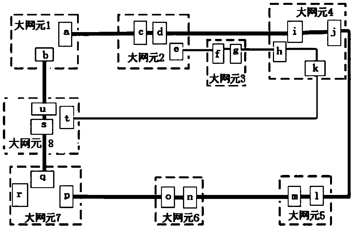
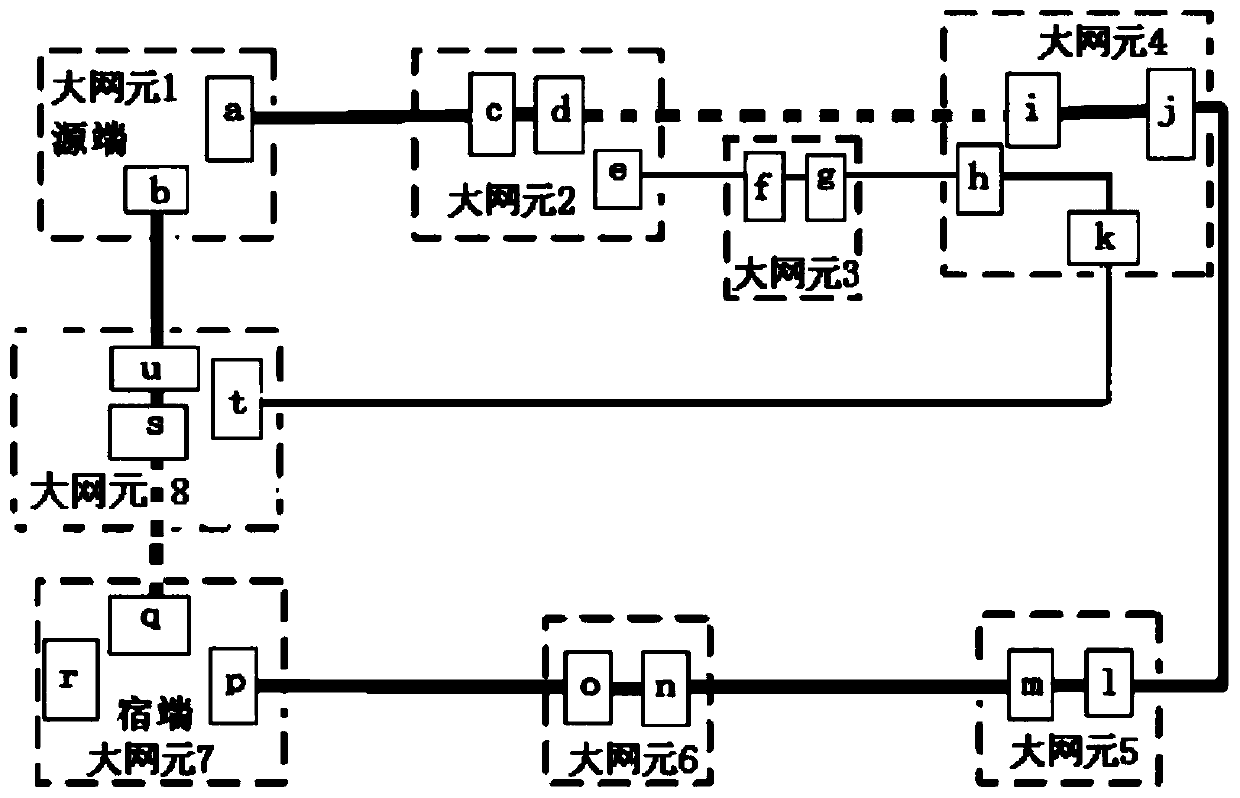
[0022] figure 1 It is a schematic diagram of the topology of the WDM transmission network applied to the automatic generation method of the WDM emergency transmission channel scheduling scheme of the present invention. figure 2 yes figure 1 The schematic diagram of the WDM transmission network in which both the two main channel routes in the above are faulty or circuit interrupted. image 3 It is a schematic diagram of the WDM emergency transmission channel path analysis process. Figure 4 is directed at figure 2 interrupted circuit conditions that occur in the image 3 An emergency transmission channel scheduling scheme obtained from the analysis process. refer to Figure 1 to Figure 2 As shown, an automatic generation method of WDM emergency transmission channel scheduling scheme is established based on WDM transmission basic configuration data, including large ...


PUM


Abstract

The invention discloses an automatic generation method of a wavelength division emergency transmission channel scheduling scheme. A large network element and a small network element which are formed on the basis of wavelength division transmission basic configuration data are established, wavelength division transmission network topological graphs of a main wave path router and a standby wave pathrouter, when the main wave path router is interrupted, an interruption service source end large network element, a host end large network element and an interruption paragraph are determined, a wavelength division emergency transmission channel scheduling generation model software algorithm is combined, an optimal wavelength division emergency transmission channel scheduling scheme can be obtained, and therefore rapid scheduling of an emergency transmission channel is effectively supported.

Description

technical field [0001] The present invention relates to WDM network transmission and communication resource management technologies, in particular to a method for automatically generating a WDM emergency transmission channel scheduling scheme, which includes large network elements and small network elements formed based on WDM transmission basic configuration data, The WDM transmission network topology diagram of the main channel routing and backup channel routing. When the main channel routing is interrupted, determine the source-end large network element, the sink-end large network element, and the interruption section. Combined with WDM emergency The transmission channel scheduling generation model software algorithm can obtain the optimal WDM emergency transmission channel scheduling scheme, thereby effectively supporting the rapid dispatch of emergency transmission channels. Background technique [0002] Traditional WDM is still widely used on the live network. Since tr...

Claims


Application Information

Patent Timeline
IPC IPC(8): H04J14/02H04B10/038H04Q11/00
CPCH04B10/038H04J14/0201H04J14/0293H04Q11/0005H04Q2011/0037
Inventor 唐慧
Owner 北京直真科技股份有限公司
Learn More