Manufacturing method of backlight source transflective film layer, backlight source and UV ink printer

A production method and backlight technology, applied in the field of microdisplay, can solve the problems of uneven light mixing, uneven light mixing on the front of surface light sources, affecting market competitiveness, etc., to achieve uniform light distribution and improve product yield.

Inactive Publication Date: 2020-05-26
BOE TECH GRP CO LTD +1
View PDF4 Cites 0 Cited by
  • Summary
  • Abstract
  • Description
  • Claims
  • Application Information

AI Technical Summary

Problems solved by technology

Due to the Lambertian distribution of the light emitted by the Mini LED chips and the certain distance between the Mini LED chips, the uneven light mixing on the front of the surface light source has become one of the major challenges currently faced.
The traditional solution solves the problem of uneven light mixing on the front of the Mini LED surface light source by increasing the OD value, but this will cause the thickness of the Mini LED surface light source to increase significantly compared with the traditional backlight source, affecting its market competitive advantage

Method used


Image

  • Manufacturing method of backlight source transflective film layer, backlight source and UV ink printer
  • Manufacturing method of backlight source transflective film layer, backlight source and UV ink printer
  • Manufacturing method of backlight source transflective film layer, backlight source and UV ink printer

Examples


Embodiment Construction

[0033] The following will clearly and completely describe the technical solutions in the embodiments of the present invention with reference to the accompanying drawings in the embodiments of the present invention. Obviously, the described embodiments are only some, not all, embodiments of the present invention. Based on the embodiments of the present invention, all other embodiments obtained by persons of ordinary skill in the art without making creative efforts belong to the protection scope of the present invention.

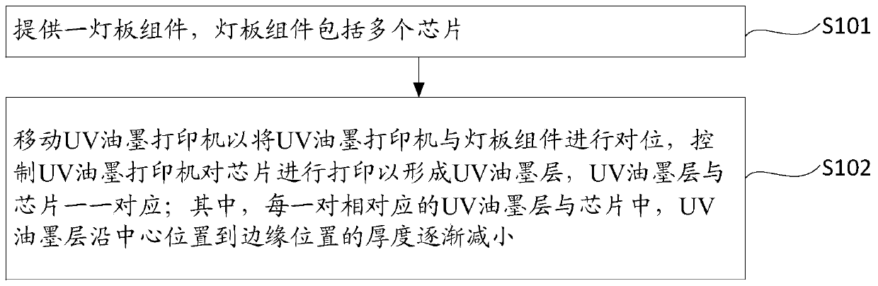
[0034] Please refer to figure 1 , the invention provides a method for manufacturing a backlight transflective film layer, comprising:

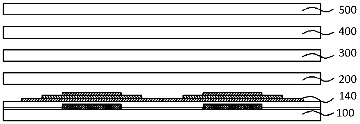
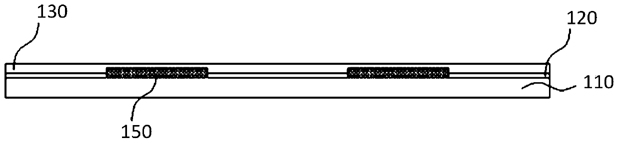
[0035] S101: Provide a light board assembly 100, the light board assembly 100 includes a plurality of chips 150;

[0036] S102: Align the UV ink printer with the lamp panel assembly 100, move the UV ink printer to print the chip 150 to form the UV ink layer 140, and the UV ink layer 140 corresponds to the chip 150 one by one;...


PUM


Abstract

The invention relates to the technical field of micro-display, and discloses a manufacturing method of a backlight source transflective film layer, a backlight source and a UV ink printer. The manufacturing method comprises the steps of providing a lamp panel assembly, wherein the lamp panel assembly comprises a plurality of chips; and moving the UV ink printer to align the UV ink printer with thelamp panel assembly, and controlling the UV ink printer to print the chips to form UV ink layers which are in one-to-one correspondence with the chips, wherein in each pair of corresponding UV ink layer and chip, the thickness of the UV ink layer is gradually reduced from the central position to the edge position. According to the manufacturing method disclosed by the invention, it can be ensuredthat the light distribution of the Mini LED chip in the light emitting angle is more uniform, and the product yield is greatly improved.

Description

technical field [0001] The present application relates to the field of micro-display technology, in particular to a method for making a transflective film layer of a backlight source, a backlight source and a UV ink printer. Background technique [0002] Mini-LED (submillimeter light-emitting diode) has many advantages such as ultra-thin, high brightness, energy saving, extremely narrow frame, HDR (high dynamic range image), high color gamut, etc., and has become a hot spot in the current market development. Due to the Lambertian distribution of the light emitted by Mini LED chips, and there is a certain distance between each Mini LED chip, resulting in uneven light mixing on the front of the surface light source, this has become one of the major challenges we are currently facing. The traditional solution solves the undesirable phenomenon of uneven light mixing on the front of the Mini LED surface light source by increasing the OD value, but this will cause the thickness of...

Claims


Application Information

Patent Timeline
Patent Type & Authority Applications(China)
IPC IPC(8): H01L33/48H01L33/46H01L25/16H01L25/00B41J3/407
CPCB41J3/407H01L25/167H01L25/50H01L33/46H01L33/48
Inventor 谢俊杰韩波张冰高亮谭叶舟桑建
Owner BOE TECH GRP CO LTD
Why Eureka
Try Eureka