An automatic inflation device with face recognition function and its inflation method
A face recognition and inflatable device technology, applied in character and pattern recognition, vehicle exterior cleaning device, vehicle cleaning, etc., can solve the problems of private use of inflatable equipment, limited automation effect, too many people in the repair shop, etc., to achieve Improve the effect of automation, ensure the effect of automatic lifting and save labor
- Summary
- Abstract
- Description
- Claims
- Application Information
AI Technical Summary
Problems solved by technology
Method used
Image
Examples
Embodiment 1
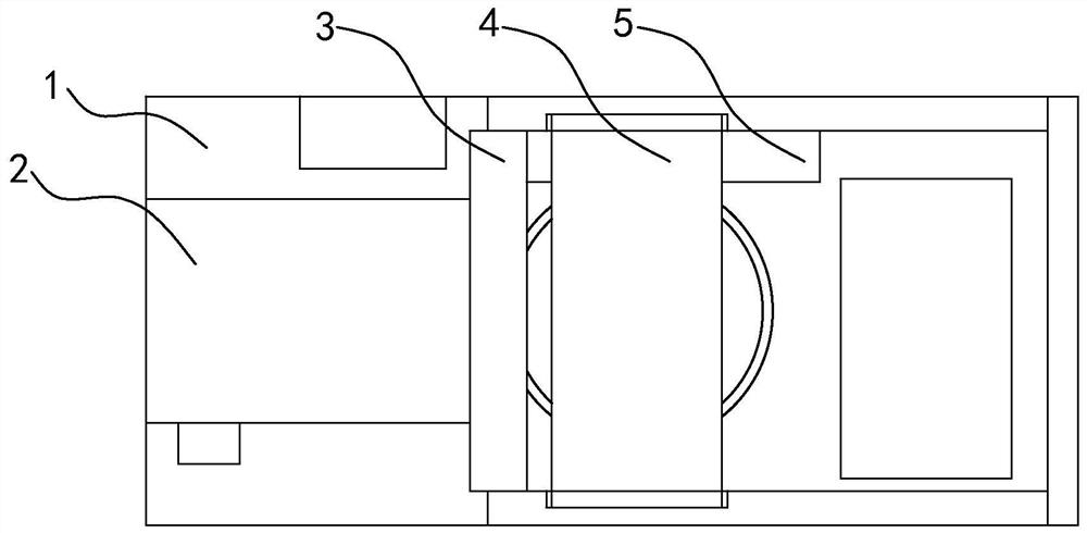
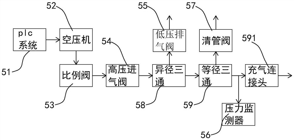
[0051] Such as Figure 1-2 As shown, the present invention discloses an automatic inflation device with a face recognition function, including a workbench 1. In a specific embodiment of the present invention, a transportation device 2, an automatic positioning device 3 and an automatic The fixing device 4 and the plc intelligent inflation control system 5; the plc intelligent inflation control system 5 includes a plc system 51, an air compressor 52 installed on the workbench 1, a proportional valve 53, a high-pressure intake valve 54, and a low-pressure exhaust valve 55. A pressure monitor 56 and a pigging valve 57 for real-time monitoring of the tire internal air pressure; the plc system 51 is electrically connected to the circuit system on the air compressor 52; the proportional valve 53 is installed on the output of the air compressor 52 end, the output end of the proportional valve 53 communicates with the high-pressure intake valve 54 through the first branch pipe; A thi...
Embodiment 2
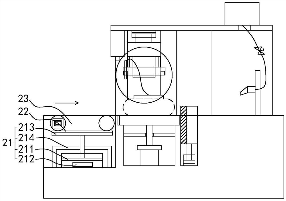
[0057] Such as Figure 3-4 As shown, in a specific embodiment of the present invention, the transportation device 2 includes a lifting part 21 fixedly installed on the workbench 1, a mounting bracket 22 and a transportation part 23 installed on the mounting bracket 22; the mounting bracket 22 passes The lifting part 21 is installed on the workbench 1 ; the transport part 23 includes a conveyor belt 231 and a first drive motor 232 for driving the conveyor belt; the first drive motor 232 is fixedly installed on the workbench 12 .
[0058] In a specific embodiment of the present invention, the lifting part 21 includes a driving cylinder 211, a cylinder controller 212, a lifting platform 213, and a stabilizing bracket 214 that passes through the air rod of the driving cylinder 211 longitudinally; On the platform 1, the output end of the air rod is vertically upward, and the cylinder controller 212 is electrically connected with the plc system 51; the bottom of the lifting platform...
Embodiment 3
[0061] Such as Figure 5-7 As shown, in a specific embodiment of the present invention, the automatic positioning device 3 includes an automatic tire positioning device and an automatic valve core positioning device 32, and the automatic tire positioning device includes a suspension beam frame 311, an infrared detector 312, a positioning platform 313 and Blocking assembly 314; the suspension beam frame 311 is fixedly installed on the workbench 1 through several columns 33; a longitudinal slideway 331 is provided on the column 33 below the suspension beam frame 311, and a sliding beam 332 is installed in the longitudinal slideway 331; A hydraulic cylinder 333 for driving the sliding beam 332 to slide longitudinally is installed on the suspension beam frame 311; the infrared detector 312 is fixedly installed on the suspension beam frame 311 between the transport device 2 and the positioning platform 313; the transport device 2 outputs The workbench 1 on the side is provided with...
PUM
 Abstract
Description
Claims
Application Information
 - R&D
- Intellectual Property
- Life Sciences
- Materials
- Tech Scout
- Unparalleled Data Quality
- Higher Quality Content
- 60% Fewer Hallucinations
Browse by: Latest US Patents, China's latest patents, Technical Efficacy Thesaurus, Application Domain, Technology Topic, Popular Technical Reports.
© 2025 PatSnap. All rights reserved.Legal|Privacy policy|Modern Slavery Act Transparency Statement|Sitemap|About US| Contact US: help@patsnap.com


