A wafer cleaning machine for physiotherapy instrument production

The technology of a physical therapy device and a cleaning machine is applied in the field of wafer cleaning machines for the production of physical therapy devices. The effect of bumping and scratching, preventing force bumping

Inactive Publication Date: 2021-04-27
南京浦口科创投资集团有限公司
View PDF7 Cites 0 Cited by
  • Summary
  • Abstract
  • Description
  • Claims
  • Application Information

AI Technical Summary

Problems solved by technology

[0005] Aiming at the deficiencies in the prior art, the object of the present invention is to provide a wafer cleaning machine for the production of physiotherapy instruments, to solve the problems in the prior art that the wafers are round and need to be cleaned in all directions when using ultrasonic waves for cleaning. In this process, the upper surface will be blocked and cannot be cleaned. When using the cleaning brush for auxiliary cleaning, the cleaning brush will touch the wafer or drive the wafer to the outside to contact the inner wall of the cleaning tank, resulting in scratches on the surface of the wafer. marks, which affect the effect of the wafer when it is made into an integrated circuit, and then make the working effect of the physiotherapy instrument poor.

Method used


Image

  • A wafer cleaning machine for physiotherapy instrument production
  • A wafer cleaning machine for physiotherapy instrument production
  • A wafer cleaning machine for physiotherapy instrument production

Examples


Embodiment 1

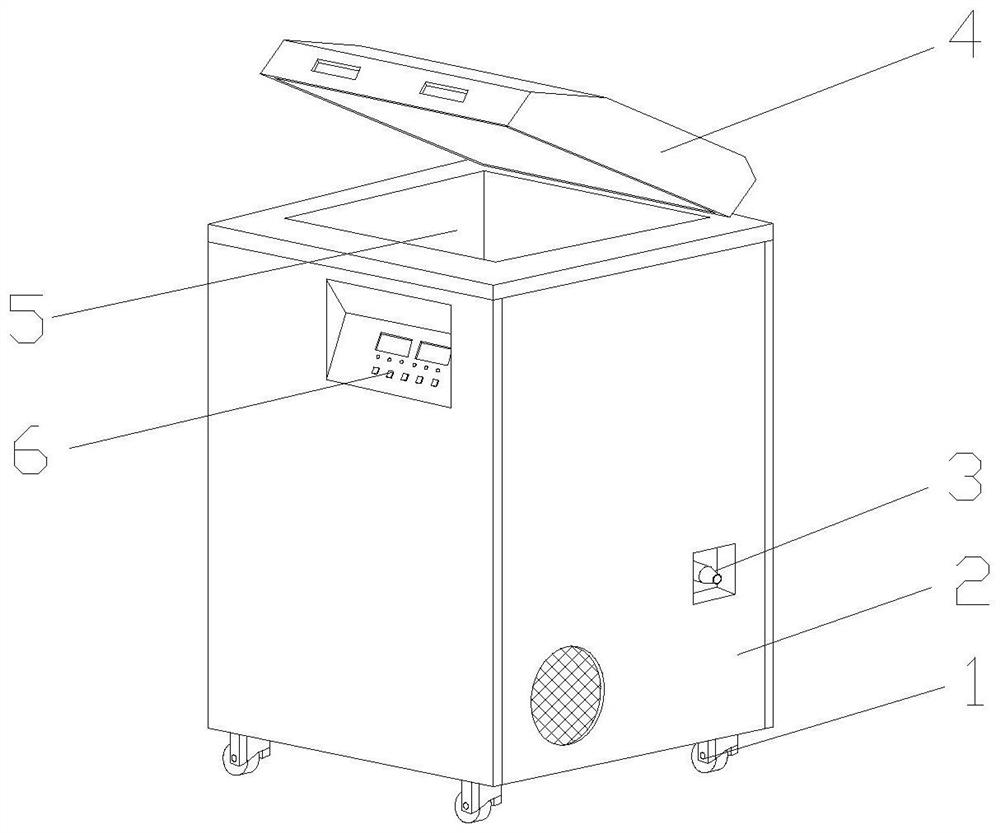
[0032] Example 1: Please refer to Figure 1-Figure 5 , the specific embodiments of the present invention are as follows:

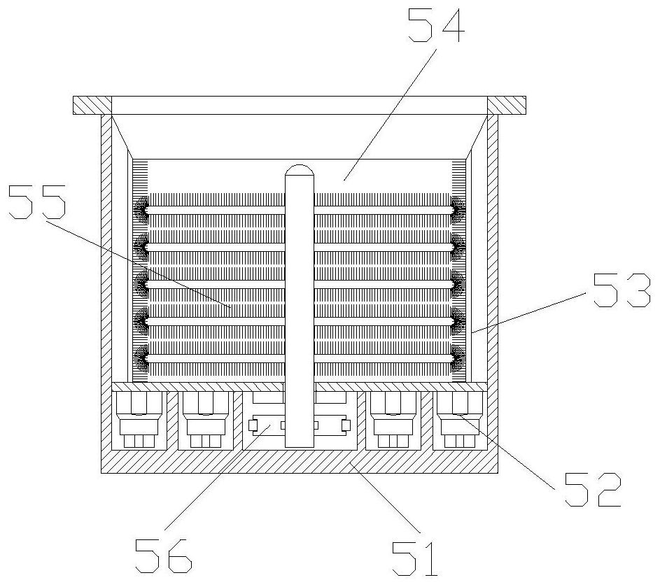
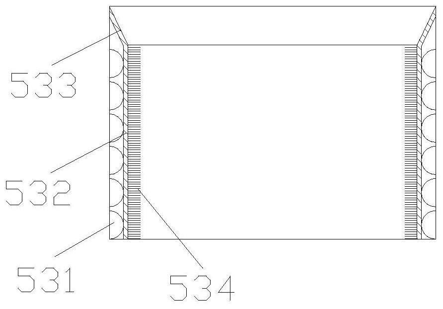
[0033] Its structure includes caster 1, cabinet 2, drain pipe 3, case cover 4, cleaning mechanism 5, control panel 6, and described caster 1 is installed on the lower end of cabinet 2 and adopts mechanical connection, and described drain pipe 3 is embedded in cabinet 2 inside and It communicates with the cleaning mechanism 5. The box cover 4 is installed horizontally on the upper end of the cabinet 2 and connected by hinges. The cleaning mechanism 5 is embedded and installed inside the cabinet 2. Electrically connected by wires; the cleaning mechanism 5 includes an outer box 51, an ultrasonic transducer 52, an inner edge protection structure 53, a cleaning chamber 54, an auxiliary cleaning structure 55, and a rotating wheel 56, and the ultrasonic transducer 52 is embedded and installed Inside the outer box 51, the inner edge protection structure 53 is emb...

Embodiment 2

[0038] Example 2: Please refer to Figure 1-Figure 2 , Figure 6-Figure 12 , the specific embodiments of the present invention are as follows:

[0039] Its structure includes caster 1, cabinet 2, drain pipe 3, case cover 4, cleaning mechanism 5, control panel 6, and described caster 1 is installed on the lower end of cabinet 2 and adopts mechanical connection, and described drain pipe 3 is embedded in cabinet 2 inside and It communicates with the cleaning mechanism 5. The box cover 4 is installed horizontally on the upper end of the cabinet 2 and connected by hinges. The cleaning mechanism 5 is embedded and installed inside the cabinet 2. Electrically connected by wires; the cleaning mechanism 5 includes an outer box 51, an ultrasonic transducer 52, an inner edge protection structure 53, a cleaning chamber 54, an auxiliary cleaning structure 55, and a rotating wheel 56, and the ultrasonic transducer 52 is embedded and installed Inside the outer box 51, the inner edge protect...


PUM


Abstract

The invention discloses a wafer cleaning machine for physiotherapy instrument production. The structure includes casters, a cabinet, a drainage pipe, a case cover, a cleaning mechanism, and a control panel. The casters are installed at the lower end of the cabinet, and the drain pipe is embedded in the inside of the cabinet. Installed on the upper end of the chassis, the cleaning mechanism is embedded and installed inside the chassis, and the control panel is installed on the front of the chassis; the cleaning mechanism includes the outer box, ultrasonic transducer, inner edge protection structure, cleaning chamber, auxiliary cleaning structure, rotating wheel, ultrasonic transducer The device is embedded and installed on the inner side of the outer box, the inner edge protection structure is embedded on the inner side of the outer box, the cleaning chamber is set on the inner side of the inner edge protection structure, and the lower end of the auxiliary cleaning structure is embedded and installed on the inner side of the outer box. The inner edge protection structure, while cleaning the wafer in all directions, buffers the parts in contact with the wafer, preventing the wafer from bumping and scratches, and better improving the effect of making the wafer into an integrated circuit .

Description

technical field [0001] The invention belongs to the field of wafer processing, and in particular relates to a wafer cleaning machine for the production of physiotherapy instruments. Background technique [0002] Physiotherapy instrument, also known as physical therapy instrument, mainly uses equipment to act on physical factors on the human body to achieve the effect of treatment, and the circuit in the physiotherapy instrument needs to use wafers to make integrated circuits to make the equipment run. Therefore, crystal The circle plays a big role in it, and the wafer needs to be cleaned after the production is completed in order to play a better role. If the wafer is not cleaned cleanly or there are scratches on the surface that affect the smoothness of the wafer surface, it will affect the smoothness of the wafer surface. To the working effect of physical therapy instrument, but there are following deficiencies in the prior art: [0003] Since the wafer is round and needs...

Claims


Application Information

Patent Timeline
Patent Type & Authority Patents(China)
IPC IPC(8): B08B3/12B08B1/00B08B1/04B08B3/10H01L21/67
CPCB08B1/002B08B1/04B08B3/10B08B3/12H01L21/67046
Inventor 闫玉飞
Owner 南京浦口科创投资集团有限公司
Why Eureka
Try Eureka